Sec 2: 8-36 Disassembly/Reassembly Procedures: Radio Reassembly
8.9.1.6 Assemble Main Housing Assembly (A, L, M)
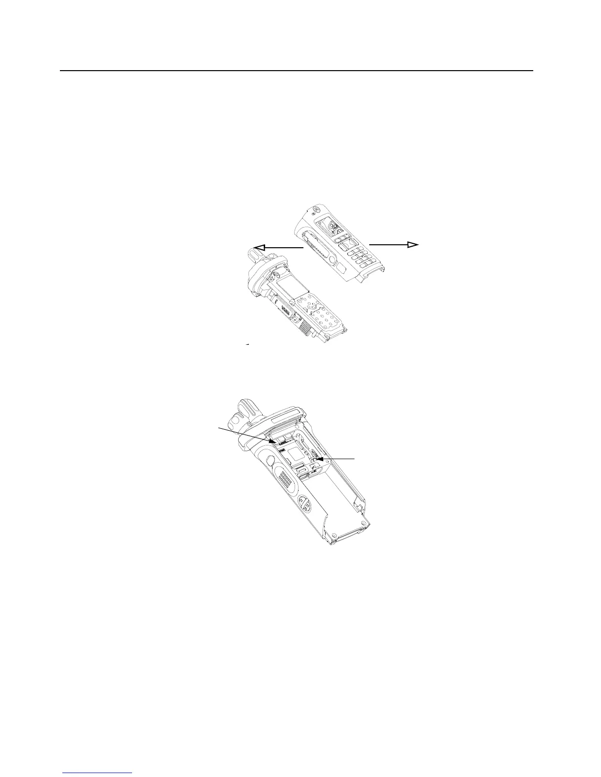
1. Stretch the Main Housing Assembly (A, L, M) side walls outward with both hands just enough
to clear the Main Chassis Assembly (E) and place it onto the radio.
2. Ensure the top edge of the housing and the bottom edge of the control top are aligned as
shown in Figure 8-48.
3. Squeeze the Main Housing Assembly (A, L, M) and the Main Chassis Assembly (E) in the
battery area until the Main Housing Assembly fully snaps in place onto the Main Chassis
Assembly.
Figure 8-48. Place Housing into Main Chassis
8.9.1.7 Assemble Expansion Board Assembly (H)
Figure 8-49. Assemble Expansion Board Assembly
1. If the Control Top Assembly (F) or VOCON Board Assembly (D) was NOT removed skip to
step 2.
Connect the Control Top Flex to the VOCON Board Assembly as shown in Figure 8-49.
2. If replacing new Control Top (58) or Main Chassis Assembly (15), add Control Top Support
Pads (23) to stainless steel backers at the locations shown on Figure 8-50.
3. If the RF Board Assembly (9) was NOT removed, skip to step 4.
Carefully align the Antenna Coax Plug to the Coax Receptacle on the RF board Assembly (C)
and slide the plug in using the Black Stick. Ensure the universal connector flex is not caught
under the antenna coax cable.
4. Tuck in the Antenna Coax Cable into its grooves as shown in Figure 8-49.
Antenna Coax Cable Connector
Control Top Assembly Flex

 Loading...


