Sec 2: 8-24 Disassembly/Reassembly Procedures: Serviceable Components of the Main Sub-Assemblies
8.8.4 Servicing of RF Board Assembly
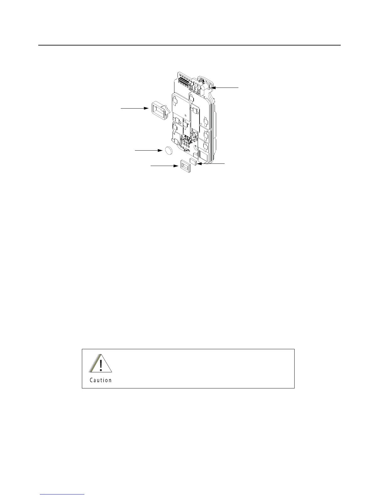
Figure 8-34. RF Board Assembly
8.8.4.1 Battery Seal
1. Complete steps 8.7.1 through 8.7.6 of section 8.7 on page 2:8-13.
2. Slide the Battery Connector Seal (13) from the battery contact header with the Black Stick.
3. Use the Black Stick and push the new Battery Connector Seal until it is properly seated onto
the RF Board surface.
8.8.4.2 Thermal Pads
1. Complete steps 8.7.1 through 8.7.6 of section 8.7 on page 2:8-13.
2. Scrape off both thermal pads (10 and 11) from the amplifiers and / or Main chassis with the
Black Stick.
3. Ensure there are no debris or residue left on the amplifier's surfaces.
4. Replace with new thermal pads.
5. Peel off the back liner from the thermal pads.
6. Insert the Outer Thermal Pad (10) into the shield opening. Make sure the bottom surface of
the pad is mating with the top surface of the amplifiers.
7. Insert the Inner Thermal Pad (11) without compressing or deforming it.
Thermal pads should always be replaced when RF Board
assembly is removed.
Battery Connector Seal (13)
RF Board Assembly (C)
Outer Thermal Pad (10)
Inner Thermal Pad (11)
Battery
 Loading...


