Disassembly/Reassembly Procedures: Radio Reassembly Sec 2: 8-39
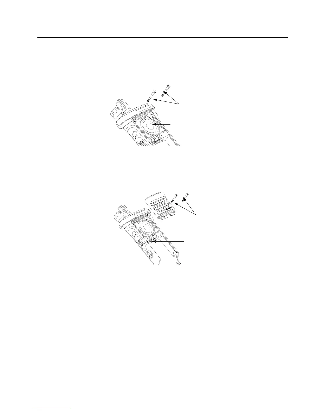
4. While holding the Speaker Module down, place the two top screws (42) into the their
respective holes and torque the screws to 10 in-lbs with an IP8 Torx Bit in a torque driver. See
Figure 8-55.
IMPORTANT: For proper sealing, Speaker Module (J) must be held down during the
torquing of the screws.
Figure 8-55. Insert Top Screws
8.9.1.9 Assemble Speaker Grille Assembly (K)
1. Install the Speaker Grille (K) by inserting the top lip under the Control Cap Assembly (58) and
rotating the grille into place. See Figure 8-56
Figure 8-56. Insert Center Screws
NOTE: Ensure the Vacuum Port Seal is in place and the Vacuum Port Seal screw shaft is
aligned with the screw hole.
2. Insert the two center screws (41) and torque to 10 in-lbs. See Figure 8-56.
Top Screws (42)
Speaker Cone
Center Screws (41)
Vacuum Port Seal

 Loading...


