Sec 1: 5-2 Performance Checks: Test Equipment Setup
Initial equipment control settings should be as indicated in Table 5-1 and should be the same for all
performance checks and alignment procedures, except as noted.
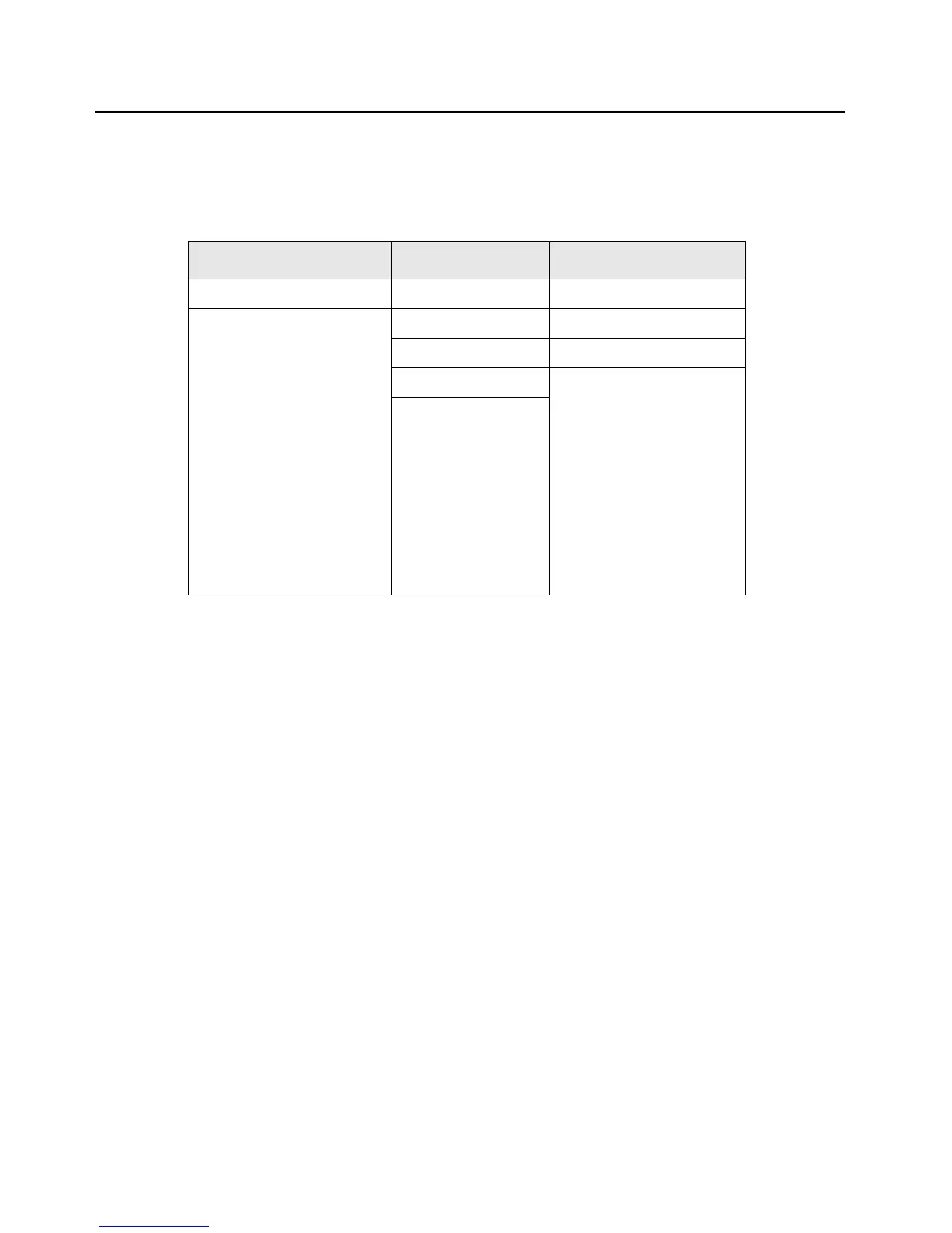
Table 5-1. Initial Equipment Control Settings
System Analyzer Test Set Power Supply
Monitor Mode: Standard* Spkr/Load: Speaker Voltage: 7.5 Vdc
Receiver Checks
RF Control: GEN
Output Level: -47 dBm
Modulation: 1kHz tone
@3 kHz deviation
Frequency: Set to selected
radio RX frequency
Meter: AC Volts
Transmitter Checks
RF Control: MONITOR
Frequency: Set to selected
radio TX frequency
Meter: RF Display
Modulation Type: FM
Attenuation: 20 dB
PTT: OFF (center) DC On/Standby: Standby
Meter Out: RX Volt Range: 10 Vdc
Opt Sel: ON Current: 2.5 Amps
* Use “PROJ 25 STD” if testing ASTRO Conventional channels.

 Loading...


