Sec 1: 3-2 Basic Theory of Operation: Analog Mode of Operation
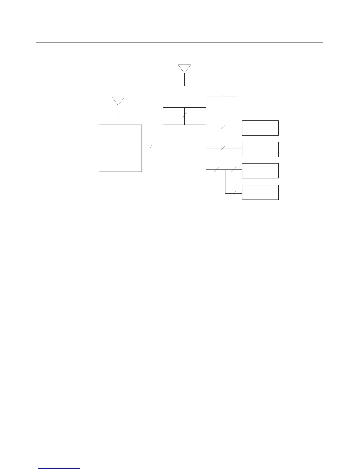
Figure 3-1. APX 5000/ APX 6000/ APX 6000Li Overall Block Diagram
3.2 Analog Mode of Operation
This section provides an overview of the analog mode receive and transmit theory of operation.
3.2.1 Receiving
The RF signal is received at the antenna and is routed through the Auxiliary and Multi Switch (SP3T) ICs on
the UHF1, UHF2 and 7/800MHz designs. The latter contains a switchable attenuator that is enabled at
predetermined RF power thresholds present at the antenna port. The VHF design does not include the
Auxiliary switch and thus RF is routed directly to the SP3T switch
. See Figure 3-2and Figure 3-5.
Antenna
Transceiver
Board
40
VOCON
Board
Expansion
Board
Bluetooth
Antenna
80
16
External Accessory Connector
External Antenna
Top Display
Controls Top
50 20
30
Front Display
Keypad
22
20

 Loading...


