Sec 1: 8-22 Disassembly/Reassembly Procedures: Serviceable Components of the Main Sub-Assemblies
4. Replace the RF Coax Cable. Bend and seat the new RF cable within the chassis grooves as
noted in step 3.
5. Torque both screws (44) with a Torx IP8 Bit and a torque Driver to 8 in-lbs.
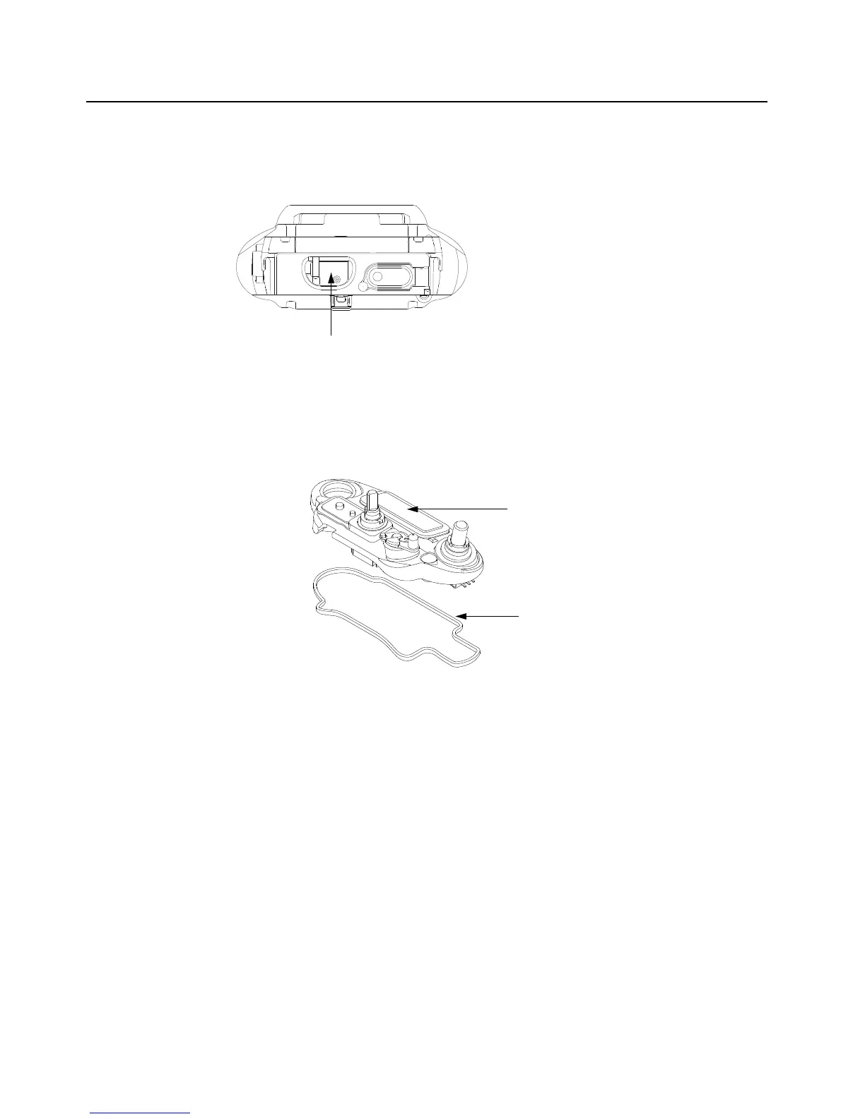
Figure 8-30. Remove Chassis Ground Contact
NOTE: There are no other serviceable components on the Main Chassis Assembly (E).
8.8.2 Servicing Control Top Assembly (F)
Figure 8-31. Control Top Assembly and Control Top Seal
8.8.2.1 Control Top Main Seal
1. Complete steps from Section 8.7.1. through Section 8.7.9. of section 8.7 on page 1:8-13.
2. Remove the Control Top Seal (22) with the Black Stick.
3. Replace the new seal into the groove provided in the Control Top Assembly's casting.
4. Ensure that seal is set properly and not stretched.
NOTE: There are no other serviceable components on the Control Top Assembly (F).
Chassis Ground Contact (18)
Control Top Seal (22)
Control Top Assembly (21)

 Loading...


