Disassembly/Reassembly Procedures: Radio Reassembly Sec 1: 8-37
4. Tuck in the Antenna Coax Cable into its grooves as shown in Figure 8-49.
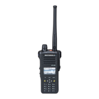
5. Plug the Expansion Board Assembly (H) to the VOCON Board Assembly (D) as shown in
Figure 8-50. Make sure the connector is fully engaged.
6. Connect the two Flex Connectors to their pairing connectors on the right and left sides of the
Expansion Board Assembly as shown in Figure 8-50.
Figure 8-50. Insert Flex Connectors
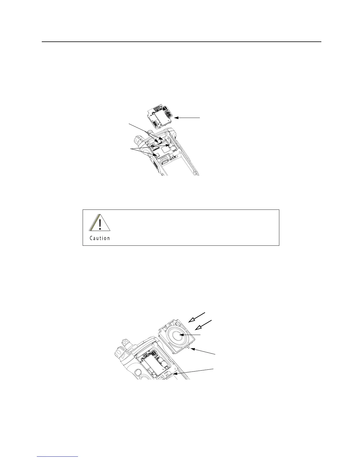
8.9.1.8 Assemble Speaker Module (J)
1. Ensure the Seal is free from any debris or foreign material.
2. Align the Speaker Module's Pin feature located on the bottom edge directly below the
speaker, into the hole on the chassis hook feature.
3. Swing the Speaker Module down and firmly press the top side into the radio as shown in
Figure 8-51.
Figure 8-51. Insert Speaker Module
Do not touch the speaker cone or the port seal. Take extra
precaution to make sure neither the speaker nor the breather
pad is damaged.
Flex Connectors
Expansion Board Assembly (33)
Control Top Support Pads
Speaker Cone
Pin Feature
Chassis Hook Feature

 Loading...