Maintenance – EP350 (Limited Keypad Model): Disassembling and Reassembling the Radio 7-17
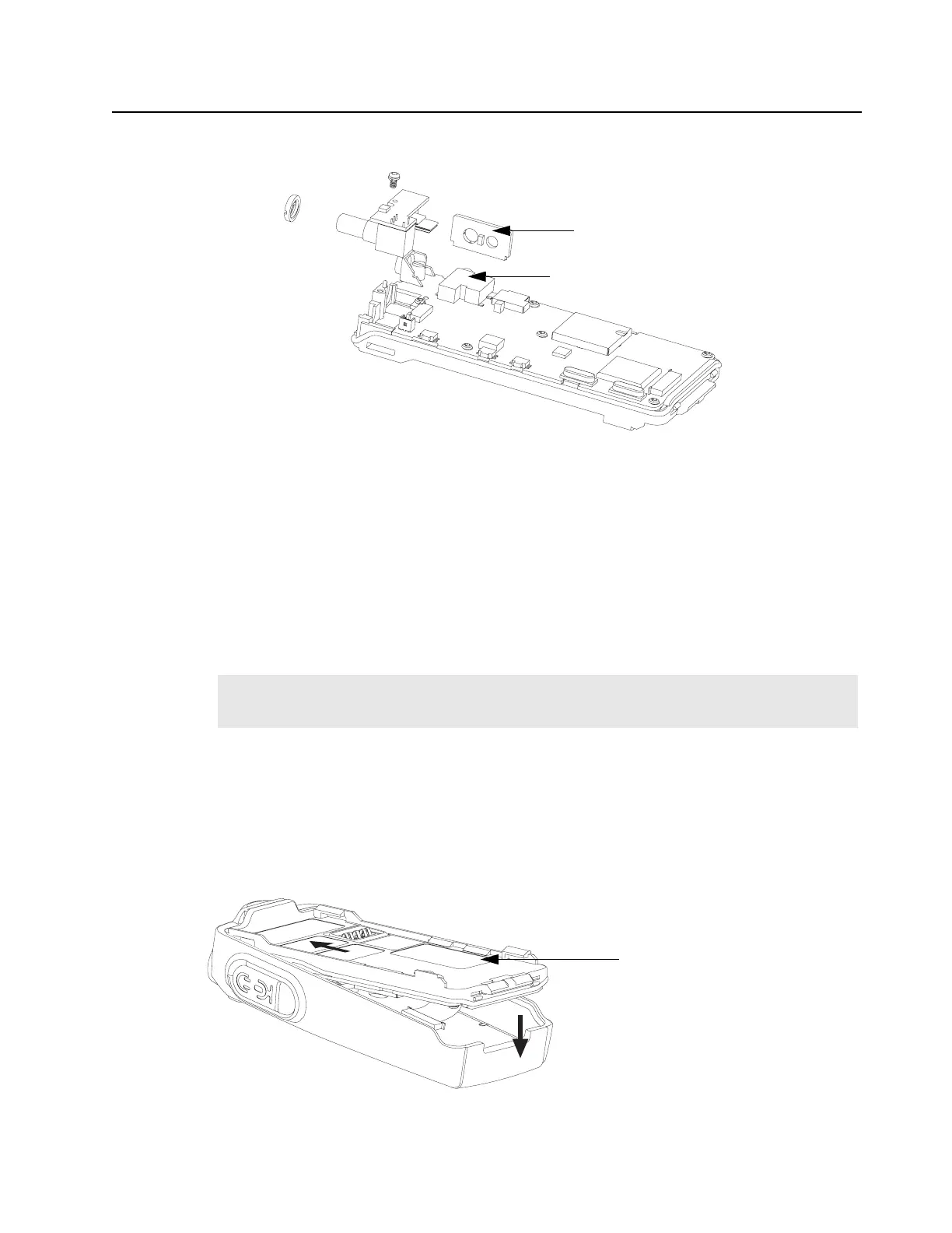
12. Align and Insert the Accessory Bracket (33) into the audio jack hole. (Refer Figure 7-55).
7.5.2.4 Chassis and Front Housing Reassembly
1. Assembly the Chassis Assembly to the Front Housing Assembly (1) as follow:
a. Lay the Chassis Assembly beside to the Front Housing Assembly.
b. Insert the Flexible Cable (37) from the main circuit board into the connector on the front
circuit board.
c. Push the latches into the Front Housing Assembly.
d. Connect the speaker wire to the connector.
2. Slide the On/Off Volume Knob Shaft into the respective holes in the front cover.
3. Insert top chassis tabs into the recesses on the front cover and apply some force until the tabs
are fully inserted.
4. Be sure the O-ring (22) is properly seated so that the radio is properly sealed.
5. Snap the bottom of the chassis into the front housing.
6. Reassemble the Knob (7), Dust Cover (41), Antenna (21), and Battery (29). (Refer Figure 7-56).
Figure 7-55. Sub Circuit Board and Accessory Bracket Reassembly
Note:
For re-use Flexible Cable (37), please ensure that it is properly folded. For new Flexible
Cable (37), please ensure pre-folded flexible cable was provided and used.
Figure 7-56. Chassis Assembly and Front Housing Assembly Reassembly
Accessory Bracket
Audio Jack
Radio Chassis

 Loading...


