Maintenance – EP350 (Full Keypad Model): Torque List 6-17
6.5.2.4 Chassis and Front Housing Reassembly
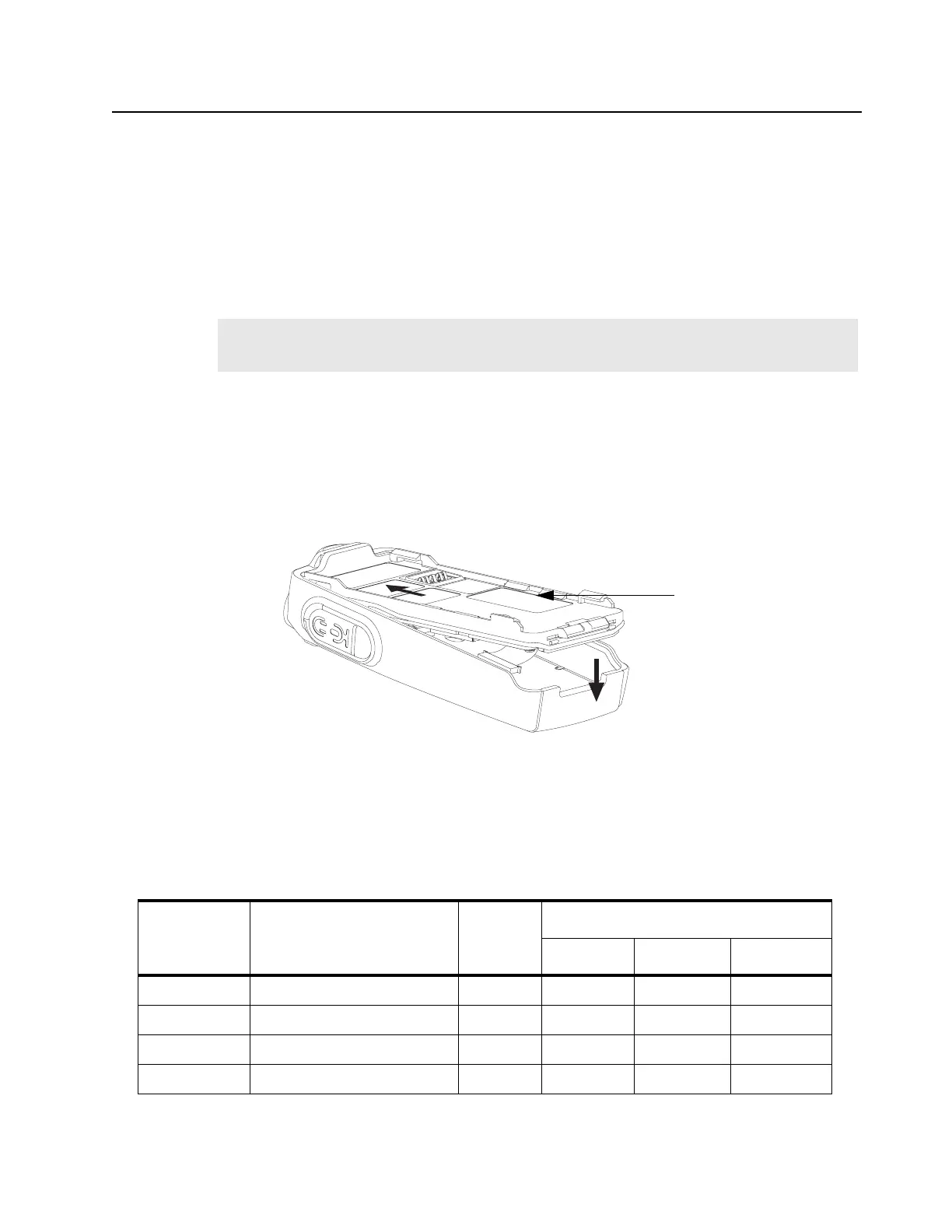
1. Assembly the Chassis Assembly to the Front Housing Assembly (1) as follow:
a. Lay the Chassis Assembly beside to the Front Housing Assembly.
b. Insert the Flexible Cable (37) from the main circuit board into the connector on the front
circuit board.
c. Push the latches into the Front Housing Assembly.
d. Connect the speaker wire to the connector.
2. Slide the On/Off Volume Knob Shaft into the respective holes in the front cover.
3. Insert top chassis tabs into the recesses on the front cover and apply some force until the tabs
are fully inserted.
4. Be sure the O-ring (22) is properly seated so that the radio is properly sealed.
5. Snap the bottom of the chassis into the front housing.
6. Reassemble the Knob (7), Dust Cover (40), Antenna (21), and Battery (29). (Refer Figure 6-35).
6.6 Torque List
Table 6-12 lists the various screws by part number and description, followed by the torque values in
different units of measure. Torque all screws to the recommended value when assembling the radio.
Note:
For re-use Flexible Cable (37), please ensure that it is properly folded. For new Flexible
Cable (37), please ensure pre-folded flexible cable was provided and used.
Figure 6-35. Chassis Assembly and Front Housing Assembly Reassembly
Table 6-12. Torque Chart
Part Number Description Quantity
Torque
N-mIb-in kgf-cm
PMDN4099_R Retainer, Speaker, with screw 1 0.11±0.01 0.95±0.09 1.10±0.10
PMDN4119_R Screw, Tapping 5 0.13±0.01 1.17±0.13 1.35±0.15
PMDN4107_R Screw, Machine 7 0.23±0.01 2.04±0.13 2.35±0.15
PMDN4114_R Screw, RF Support 1 0.23±0.01 2.04±0.13 2.35±0.15
Radio Chassis

 Loading...


