2-6 Theory Of Operation: Major Assemblies
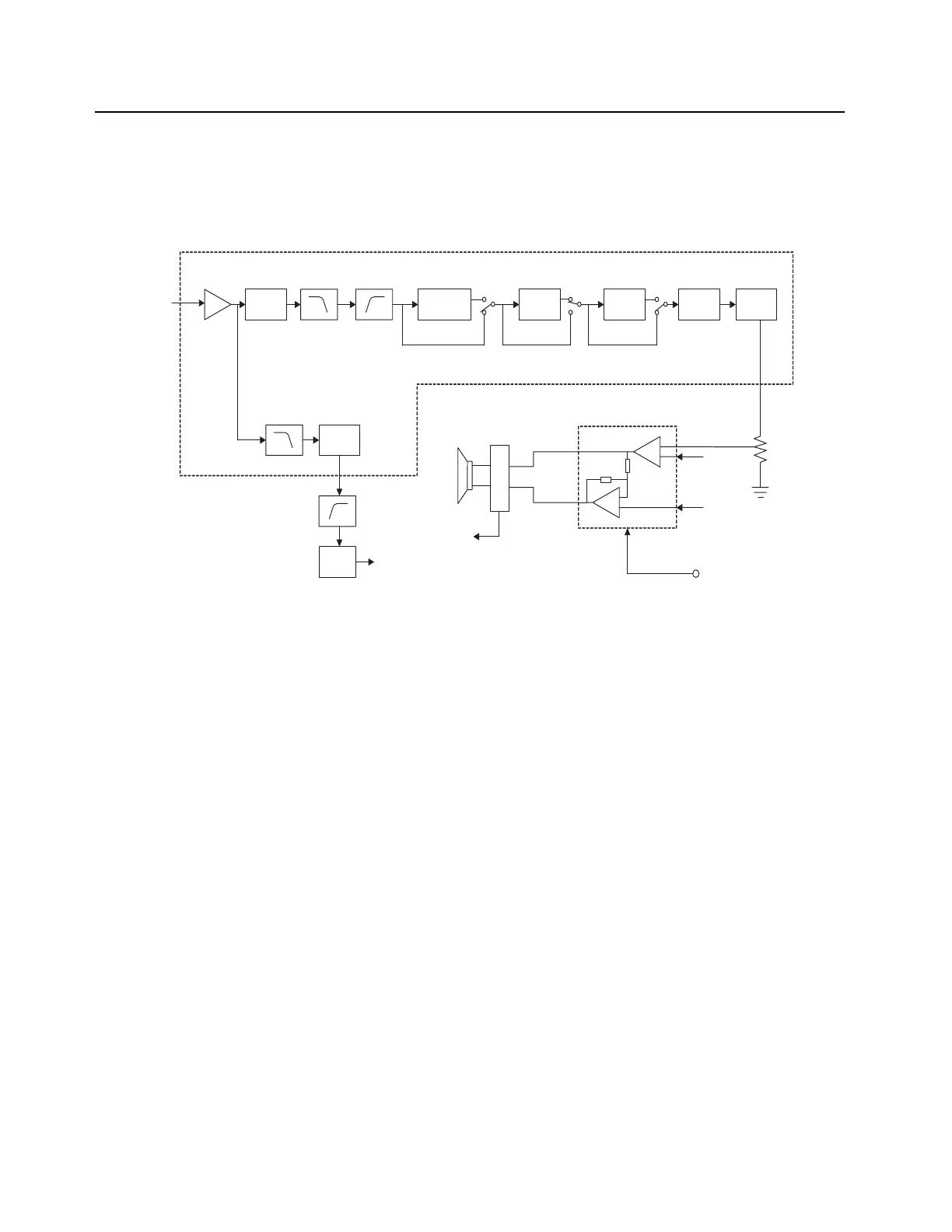
2.2.4 RX Audio Circuit
The RX audio circuit consists of Audio Processor IC, Audio amp, speakers & Sub-tone system.
The RX Audio from U201 is channeled to Audio processor IC. VR3 controls the received
demodulated signal level from -4.0 dB to +3.5 dB in 0.5 dB steps. RX LPF eliminates high-frequency
audio components > 3 kHz. TX/RX HPF eliminates low-frequency audio components lower < 250Hz.
Descrambler (if ON) inverts the spectrum distribution of audio signals with respect to scrambling
frequency. De-emphasis (if ON) restores high-frequency component of audio signal which has been
emphasized by the pre-emphasis circuit in transmitting radio. Expander (if ON) expands audio signal
by 0.5 dB to restore the original signal compressed by transmitting radio. VR4 amplifies RX audio
level by -18.0 dB, with -4.5 dB to +4.5 dB in 0.25 dB steps adjustment range. Smoothing filter (SMF)
eliminates high-frequency and clock components, generated by ASIC.
Sub-audio Programmable LPF totally eliminates voice audio from Audio signal to extract sub-audio
tone. VR5 regulates the output level of extracted sub-audio tone and sends it to a high pass filter
(U105-A,B) with 4 selectable cut-off frequencies and finally passes through a comparator (U105-C),
to square the signal and sends it to the MCU.
The output audio signal of Audio Processor IC is directed to volume control switch (SW/VOL1) which
is controlled by user and is finally amplified by U601BTL Audio Amplifier to a sufficient level to drive
either the external or internal speaker.
Figure 2-4. RX Audio Block Diagram
VR3
Scrambler /
Descrambler
De-
emphasis
Expander VR4 SMF
SVR
IN-
IN+
OUT-
OUT+
Audio Mute
control
RX LPF TX/RX HPF
RXA1
-4 to +3.5dB /
0.5dB
-18, -4.5 to + 4.5dB /
0.25dB
Audio Processor IC (AK2347)
Audio IN
(from IF IC)
VR5
Sub audio
Programmable
LPF
To CPU
(tone detect)
pin 24
pin 18
pin 21
Audio Amp.
U102
U601
Vol1
-6 to +6dB /
0.5dB
INT SPK.
EXT SPK.
J601
Sub audio
HPF
U105-A,B
Compar
ator
U105-C

 Loading...


