5-2 Radio Programming and Tuning: Radio Tuning Setup
Procedure:
1. Turn source and destination radios off.
2. Connect cloning cable (PMDN4076_R) to programming port of the two radios.
3. Turn on the destination radio.
4. Press and hold on the source radio and power up. "MASTER" and programming mode
icon are displayed on the source radio and at the same time LED of the radio turns solid amber.
5. "SLAVE" and programming mode icon are displayed on the destination radio and at the same
time LED of the radio turns solid amber.
6. During the cloning process, LED flashes in amber and source radio displays "CLONING" while
destination radio displays "PROG ON".
7. When cloning is completed, the source and destination radios display "COMPLETE". To exit
cloning mode, radios should be turn off.
8. Turn both radios off.
9. Disconnect the cloning cable from both radios and turn them on for normal operation.
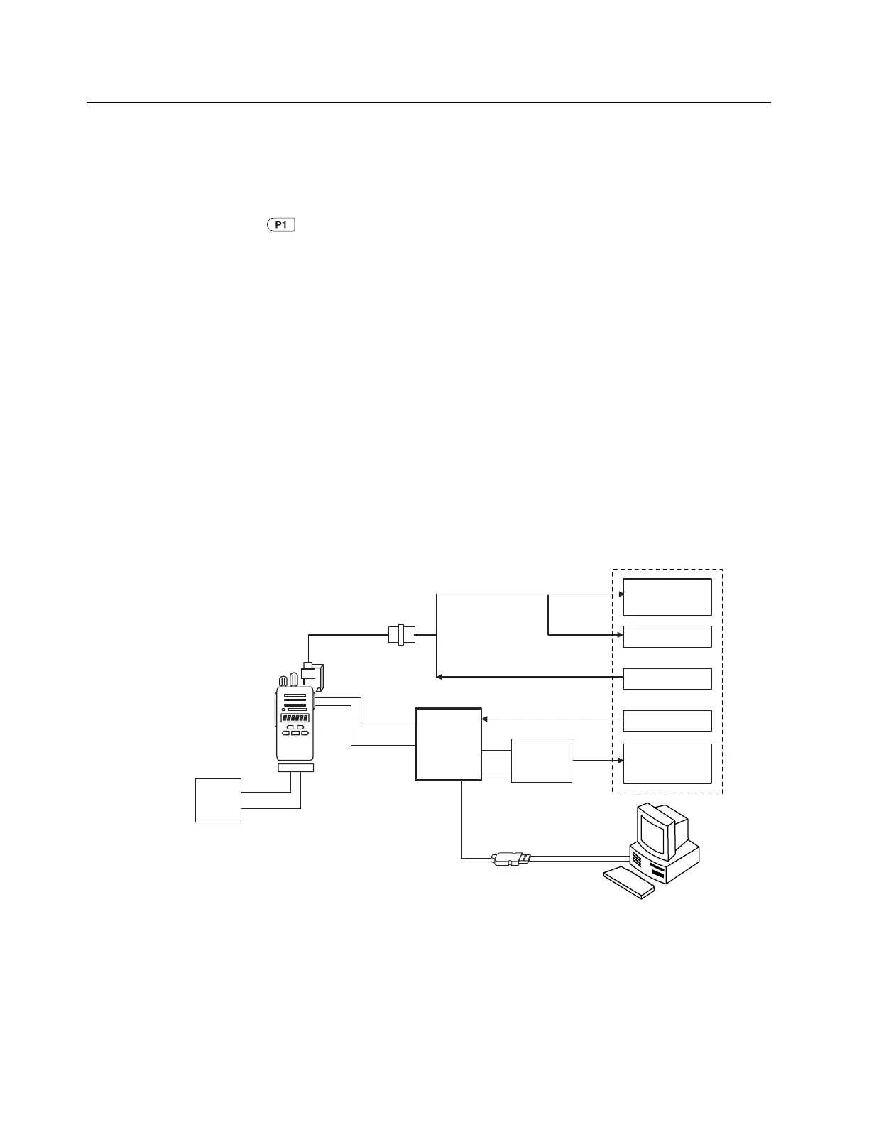
5.4 Radio Tuning Setup
A Windows 2000/XP/Vista PC (personal computer) and Entry Level Radio Tuner are required to tune
the radio. To perform the tuning procedures, the radio must be connected to the PC, Test box and
Universal Test Set as shown in Figure 5-6. Radio Tuning Setup below. Refer to online help files for the
tuning procedures.
Figure 5-6. Radio Tuning Setup
RADIO
Power
Supply
BNC
Test Box
PMDN4040_R
Audio IN
RX
RX
RX Low
TX
TX
Audio Out
RX/TX data
GND
Program/Test Cable
PMDN4077_R
Battery Eliminator
PMDN4080_R
RF adaptor
PMDN4041_R
GND plate
PMDN4079_R
1
Watt Meter
Service Monitor
or Counter
System Analyzer
RF Generator
Audio Generator
Audio Analyzer
Audio
Transformer /
Combiner
PMDN4171_R
Note: 1. Use PMDN4040BR or higher for tuning the EP350 Series radios as PMDN4040AR cannot be used to
perform this function.
2. Use PMDN4171_R for tuning the EP350 Series radios when using the service monitor R2600 series.

 Loading...


