6-10 Maintenance – EP350 (Full Keypad Model): Disassembling and Reassembling the Radio
6.5.1.2 Chassis Assembly Disassembly
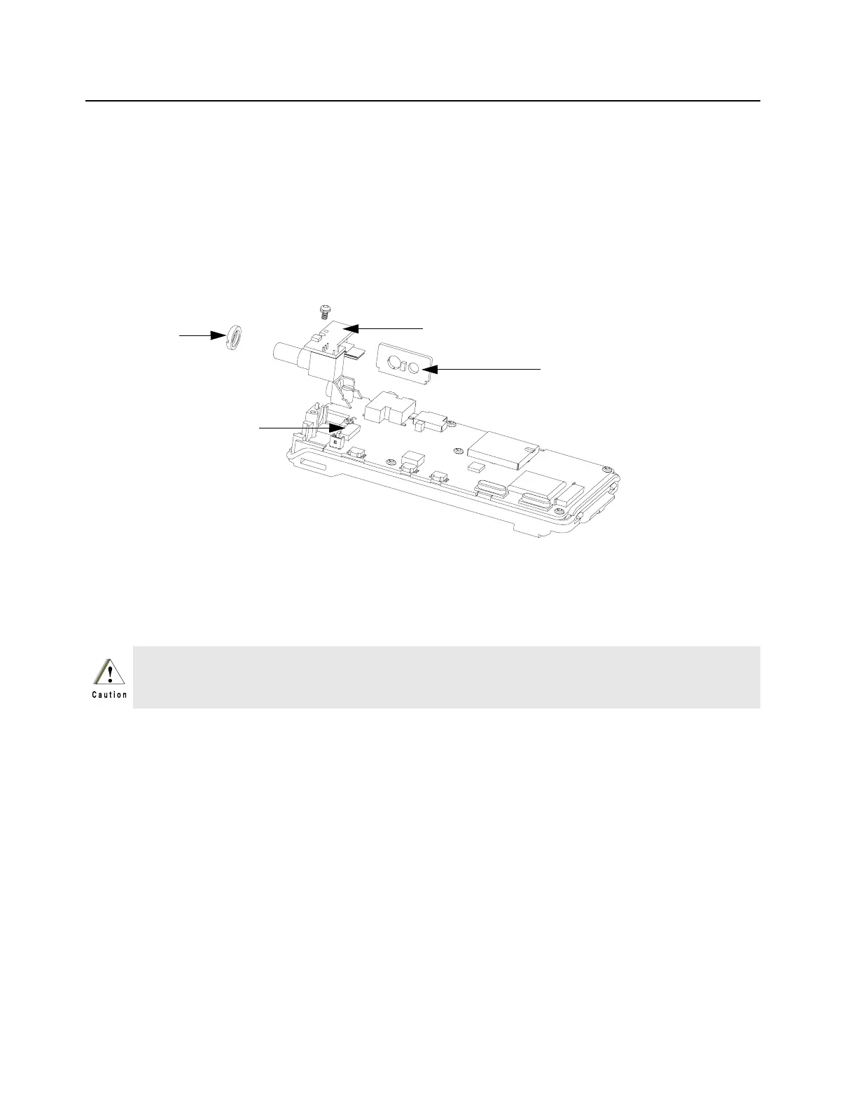
1. Remove the Accessory Bracket (33).
2. Remove the nut (16) on the On/Off Volume Knob Shaft with the Crab Eye Nut Opener.
3. Remove the screw holding the Sub Circuit Board (15) to the Chassis (25) with a Phillips
screwdriver.
4. Push the latches on the Main Circuit Board (18) to release the Flexible Cable (37) from the
connector.
5. Remove the Sub Circuit Board from the Chassis. (Refer Figure 6-23).
6. Remove the six screws (35) holding the Main Circuit Board to the Chassis with a Phillips
screwdriver. Remove the RF Support Screw (19) with a flat head screwdriver.
7. Remove the Main Circuit Board from the Chassis.
8. Remove the seven small O-ring retainers from their slots in the Chassis. Note the alignment of
the retainers for reassembly.
9. Remove the O-ring (22) and the Battery Contact Seal (26). (Refer Figure 6-24).
10. Remove the finger strips from the Chassis. Reuse the finger strips if chassis change is required
only. Note the alignment of the finger strips for assembly.
Figure 6-23. Sub-Circuit Board and Accessory Bracket Removal
Refer to the CMOS CAUTION paragraph under Section 6.3 before removing the main board. Be
sure to use ESD protection when handling the circuit boards.
Nut
Accessory Bracket
Sub Circuit Board
Latch

 Loading...


