Radio Programming and Tuning: Transmitter Alignment Options 5-5
5.5.3 Transmit Modulation Tuning
There are 2 variations of Transmit Modulation Tuning, namely 12.5 kHz and 25 kHz.
Table 5-7. Transmit Modulation Tuning
5.5.3.1 Service Monitor Setting
1. Initial setup using the 8920A RF Communications Test Set
a. Connect “RF IN/OUT” port on 8920A to RF adaptor on radio’s antenna port using a N-Type to
BNC cable. Connect “AUDIO OUT” on 8920A to “Tx MOD” on test box using a BNC to BNC
cable. Connect the rest according to Figure 5-6. Radio Tuning Setup.
b. On 8920A, select “Tx” under “SCREEN CONTROL”.
c. Using the “CURSOR CONTROL”, key in the following items:
i. Tune Mode: Auto
ii. Tune Freq: Depends on Tune Mode
- Once “Auto” is selected, the centre frequency is set to the strongest RF signal
- Once “Manual” is selected, desired frequency has to be entered manually
iii. Tx Pwr Zero: Zero
iv. Input Port: RF In
v. Ext Tx Key: Off
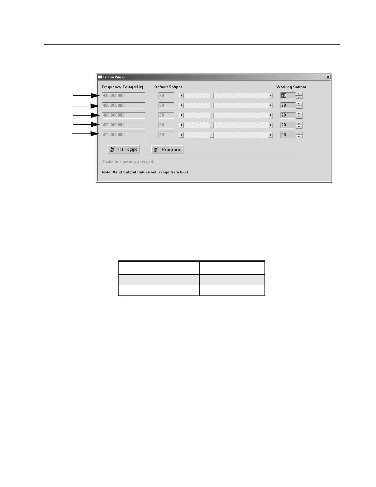
Figure 5-8. Tx Low Power Window (Low Power)
Channel Spacing (kHz) Tuning Range (kHz)
12.5 2.25 ± 0.05
25 4.5 ± 0.1
F1
F2
F3
F4
F5

 Loading...


