Radio Programming and Tuning: Transmitter Alignment Options 5-3
5.4.1 Initial Test Equipment Control Settings
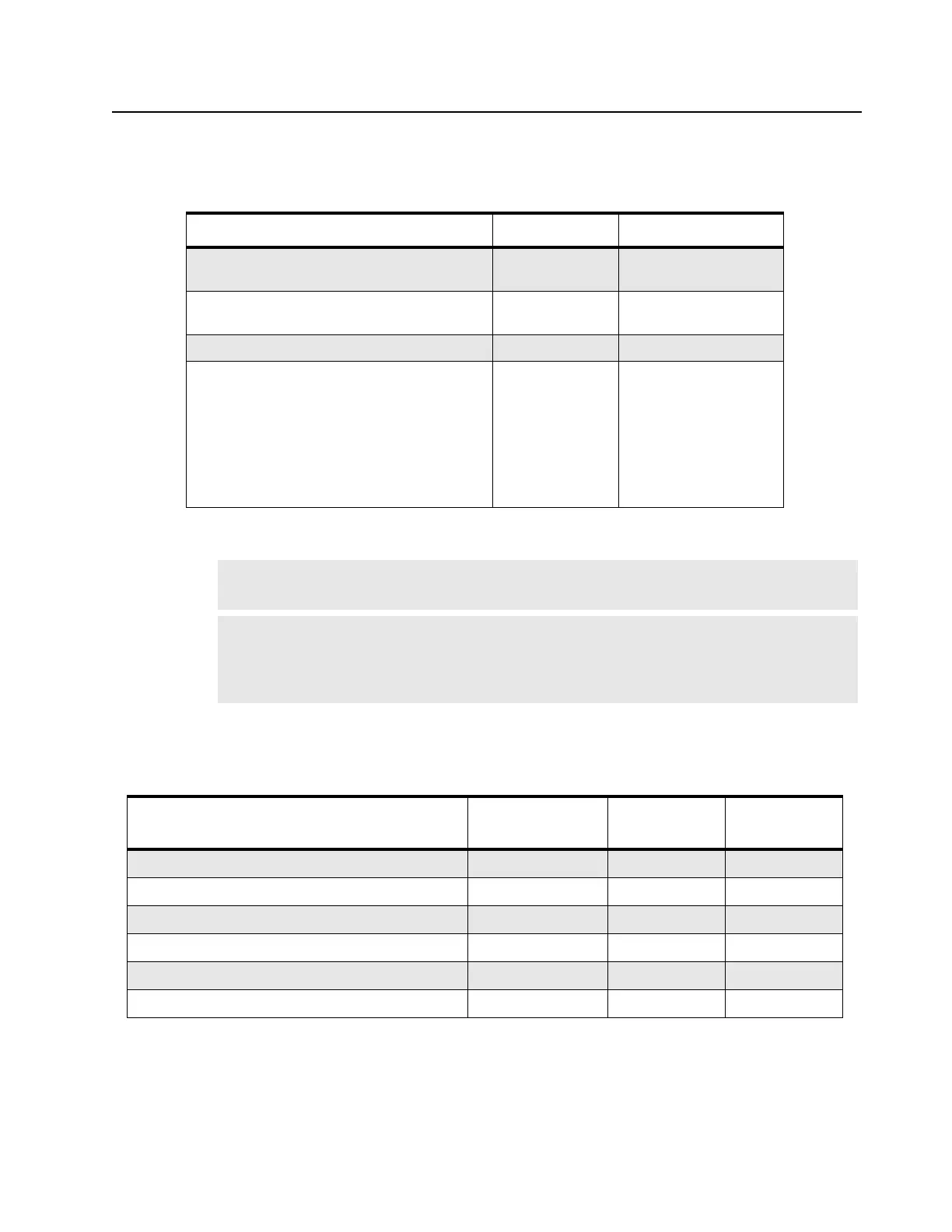
The initial test equipment control settings are listed in Table 5-5.
5.5 Transmitter Alignment Options
Table 5-6. Transmit High/Low Power Level
5.5.1 Transmit High Power Tuning
1. Click the Read icon to initiate communication with the radio.
2. Under the Alignment menu, select Tx Power, then select High (Figure 5-7. Tx High Power
Window (High Power)).
Table 5-5. Initial Equipment Control Settings
Service Monitor Test Set Power Supply
Monitor Mode: Power Monitor Impedance: 24
Ohm
Voltage: 7.5 Vdc
RF Attenuation:
-70 Speaker/load:
Load
DC on/standby: Standby
AM, CW, FM: FM PTT: OFF Volt Range: 0 – 10 V
Oscilloscope Source: Mod
Oscilloscope Horizontal: 10 mSec/Div
Oscilloscope Vertical: 2.5 kHz/Div
Oscilloscope Trigger: Auto
Monitor Image: Hi
Monitor BW: Nar
Monitor Squelch: mid CW
Monitor Volume: 1/4 CW
Current: 3.0 A
Note: The maximum available power level given in the table below must NOT be exceeded.
There are separate alignment procedures for High and Low power.
Note:
When checking the RF power output of the radio with a test set, always use a pad of
at least 30 dB attached to the radio end of the RF cable. This will avoid an RF
mismatch and ensure a stable RF reading that will not change with varying lengths of
connecting cable.
RF Band (MHz) Model Number
High Power
(W)
Low Power
(W)
435 – 480M 4W 12.5/25K 99C FKPFPP SCR _H03RDK8AA_ 4.10 – 4.35 1.05 – 1.25
435 – 480M 4W 12.5/25K 99C LKP SCR _H03RDH8AA_ 4.10 – 4.35 1.05 – 1.25
136 – 174M 5W 12.5/25K 99C SCR _H03KEK8AA_ 5.00 – 5.30 1.00 – 1.30
136 – 174M 5W 12.5/25K 99C SCR _H03KEH8AA_ 5.00 – 5.30 1.00 – 1.30
403 – 447M 4W 12.5/25K 99C FKPFPP SCR _H03QDK8AA_ 4.10 – 4.35 1.05 – 1.25
403 – 447M 4W 12.5/25K 99C LKP SCR _H03QDH8AA_ 4.10 – 4.35 1.05 – 1.25

 Loading...


