Theory Of Operation: Major Assemblies 2-7
2.2.5 TX Audio Circuit
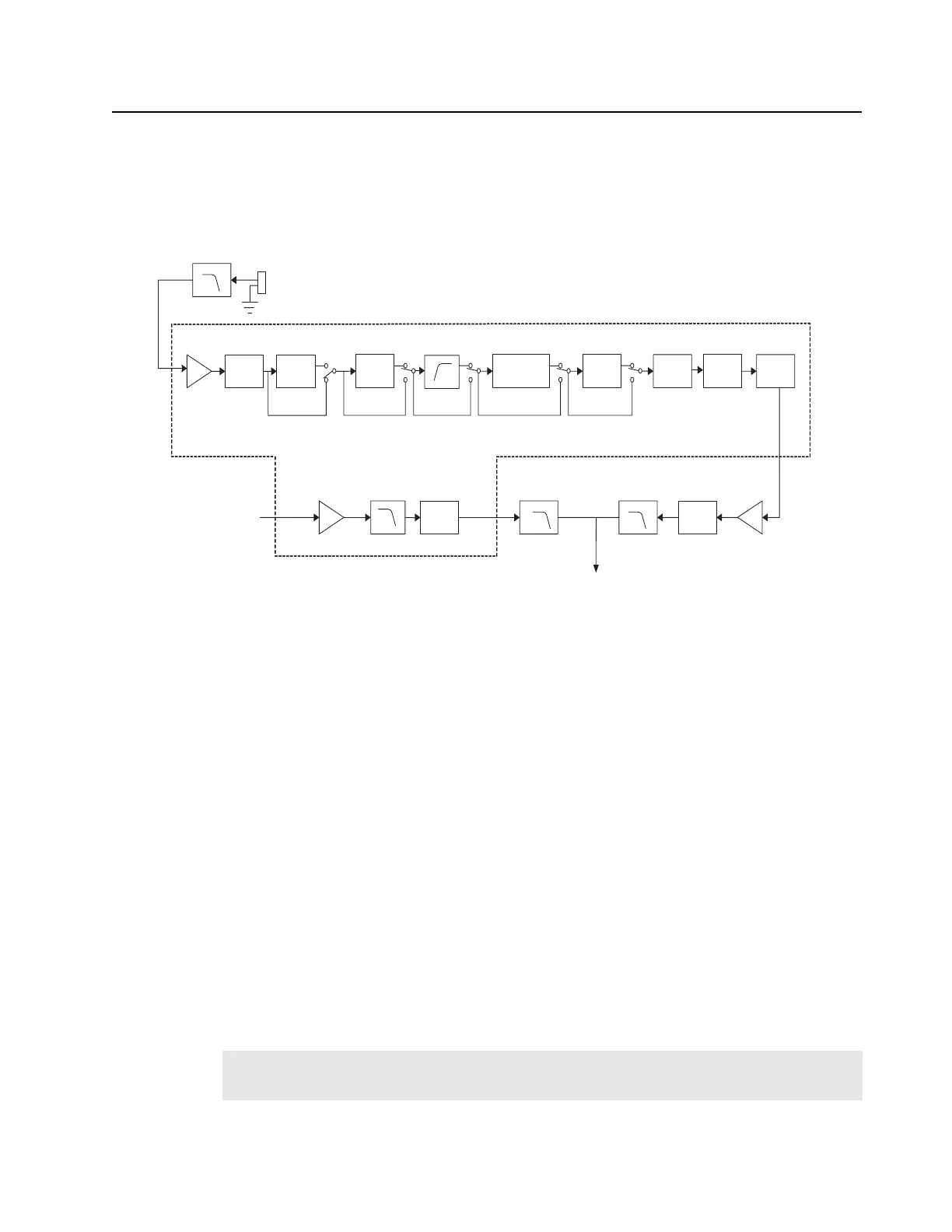
The TX audio circuit is comprised of microphones, LPF, Audio Processor IC, and TX Sub-tone
system.
The TX audio enters the radio via the internal MIC or external MIC. This TX Audio is filtered through
a 4th order 4 kHz Low-pass filter (U501-C & D) which prevents aliasing noise from ASIC. TX Audio
enters the Audio Processor IC which is then directed to an internal Amplifier (TX A1) for gain
adjustment of audio signal. A HPF (VR1) controls the input level of TX audio signal from -6.0 dB to
+4.5 dB in 1.5 dB steps. A Compressor (if ON) compresses the amplitude of TX audio signal by
0.5 dB. A Pre-emphasis circuit (if ON) emphasizes the high frequency component of TX audio signal
to improve Signal to Noise ratio before modulation. A shared High-pass filter (TX/RX HPF)
eliminates low-frequency components <250 Hz from TX audio signal. A Limiter is used to limit the
signal amplitude and suppress frequency deviation during modulation. VR2 controls the output level
from -9.6 dB to +3.0 dB in 0.2 dB steps. A Splatter (LPF) eliminates high-frequency components
>3 kHz. A Smoothing filter (SMF) eliminates high-frequency and clock components generated
internally by ASIC.
For sub-tone data from CPU, DTA1 amplifies the signal, sends it through a Sub-audio Programmable
LPF to eliminate components of DAT1 amplification, and finally the signal is regulated by VR5 from -
6.0 dB to +6.0 dB in 0.5 dB steps. The final sub-tone data passes through a 2nd order LPF (U502-A)
before it is mixed with TX Audio for modulation.
The processed TX audio signal from Audio Processor IC is amplified by TX audio frequency amplifier
(U502-C) to increase limiting range and then adjusted to a proper level for modulation by U508.
Final TX Audio signal passes through a 6th order 3 kHz low pass filter (U501-A & B) before sent to
VCO for modulation.
Figure 2-5. TX Audio Block Diagram
Note:
Retune the TX modulation if U508 is replaced. Refer Chapter 5.5: Transmitter Alignment
Options on page 5-3.
VR1
(HPF)
Limiter
Scrambler/
Descrambler
Splatter SMF
TX/RX HPF
TXA1
-6 to +4.5dB/
1.5dB
-9.6 to +3dB/
0.2dB
Audio Processor IC (AK2347)
Tone IN
(from CPU)
VR5
Sub audio
Programmable
LPF
pin4
pin17
pin8
U102
-6 to +6dB/
0.5dB
Fc=300Hz
VR2
Pre-
Emphasis
Com-
pressor
DTA1
pin19
To VCO &
VCTCXO
2 Order LPF
(Fc=300Hz)
U502-A
Mod.Adj,
6 Order LPF
(Fc=3KHz)
U501-A,B
U508
TX AF Amp.
U502-C
4 Order LPF
(Fc=4KHz)
U501-C,D
Mic
(Audio IN)
Fc=2.55KHz/
3KHz

 Loading...


