2 - 14 MC70 Integrator Guide
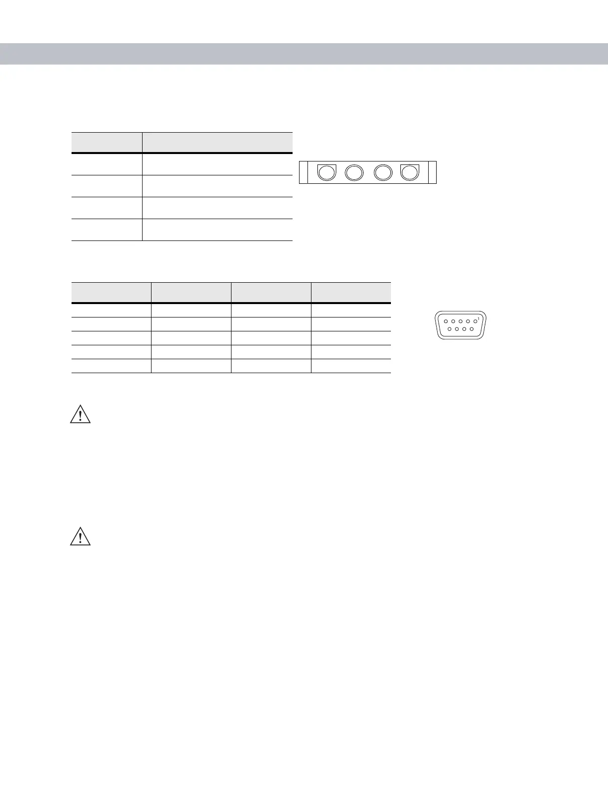
Connector Pin-Outs
Mounting the Cradle
1. Select a mounting location for the cradle. It should be flat, and must provide adequate support for the
cradle.
2. Prepare the mounting surface to accept four #8-32 studs, using the mounting template below. Drill four
holes with a #6 drill bit.
Table 2-4
Power Input Cable
Pin Signal
1 Chassis ground (Bare Wire)
2 Chassis ground (Bare Wire)
3V+ (Red Wire)
4V+ (Red Wire)
Table 2-5
Serial Cable
Pin Signal Pin Signal
1 DCD 5 GND
2RxD 6DSR
3TxD 7RTS
4DTR 8CTS
5GND 95V_OUT
CAUTION ROAD SAFETY - Do not use the EDA while driving. Park the vehicle first. Always ensure the EDA
is fully inserted into the cradle. Do not place it on the seat or where it can break loose in a collision
or sudden stop. Lack of proper insertion may result in property damage or personal injury. Symbol
Technologies, Inc. is not responsible for any loss resulting from the use of the products while
driving. Remember: Safety comes first.
1
Connector on Power Cable
Connector on Serial Cable
CAUTION Only mount the Vehicle Cradle in a vertical position with the release level at the top or in a horizontal
position with the EDA display facing up. Never mount the vehicle cradle on the side or upside down or
on a wall that can be subject to impact or collision of greater than 40Gs, in accordance with SAE J1455
Section 4.10.3.5
 Loading...