USER MANUAL OPTIMA 7
MRU GmbH, D-74172 Neckarsulm 12 / 78
3 Description
The main task of the analyzer is to assist with precision control and ad-
justment measurements of gas, oil and wood fired furnaces.
Available options for this and other analyzers can be found on the MRU
Homepage or speak to a member of our sales team.
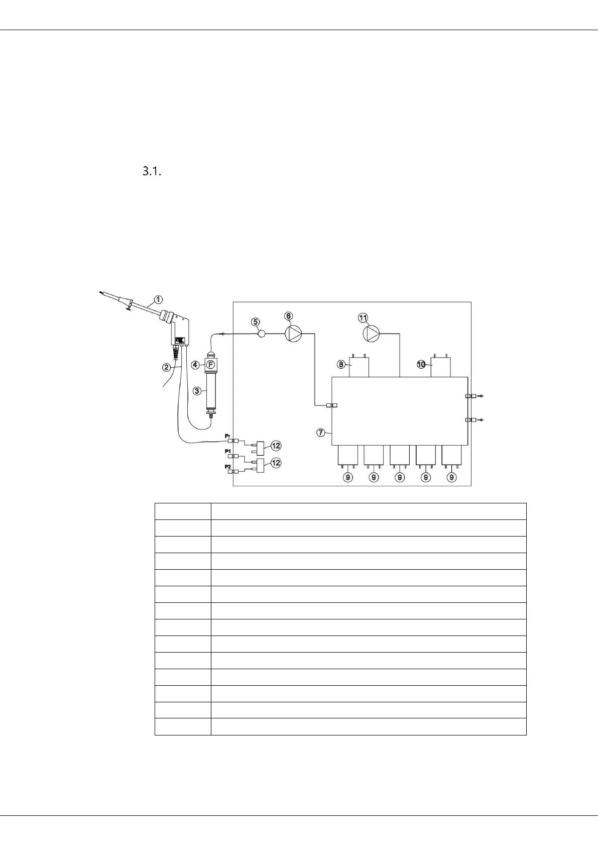
Gas schematics diagram
In combination with the extraction probe (inserted in the stack) the in-
ternal gas pump of the OPTIMA7 analyzer extracts a portion of the flue
gas and analyzes it using electro-chemical sensors.
The thermo-element in the probe tube measures the flue gas tempera-
ture and due to the construction of the probe pressure (draft) can be
measured as well.