SUPREMATouch
44
Operation of the System
MSA
US
Sensors Submenu
Through the submenu "Sensors", the parameters of the predefined remote sensing heads can be
viewed as well as set for some predefined parameter in specific ranges. The menu contains the
following items described consecutively in this section:
- Head parameters
- Status texts
- Gas name
- Measuring range
- Dimensions
- Lin.- tables
- Assignment
- Allocation
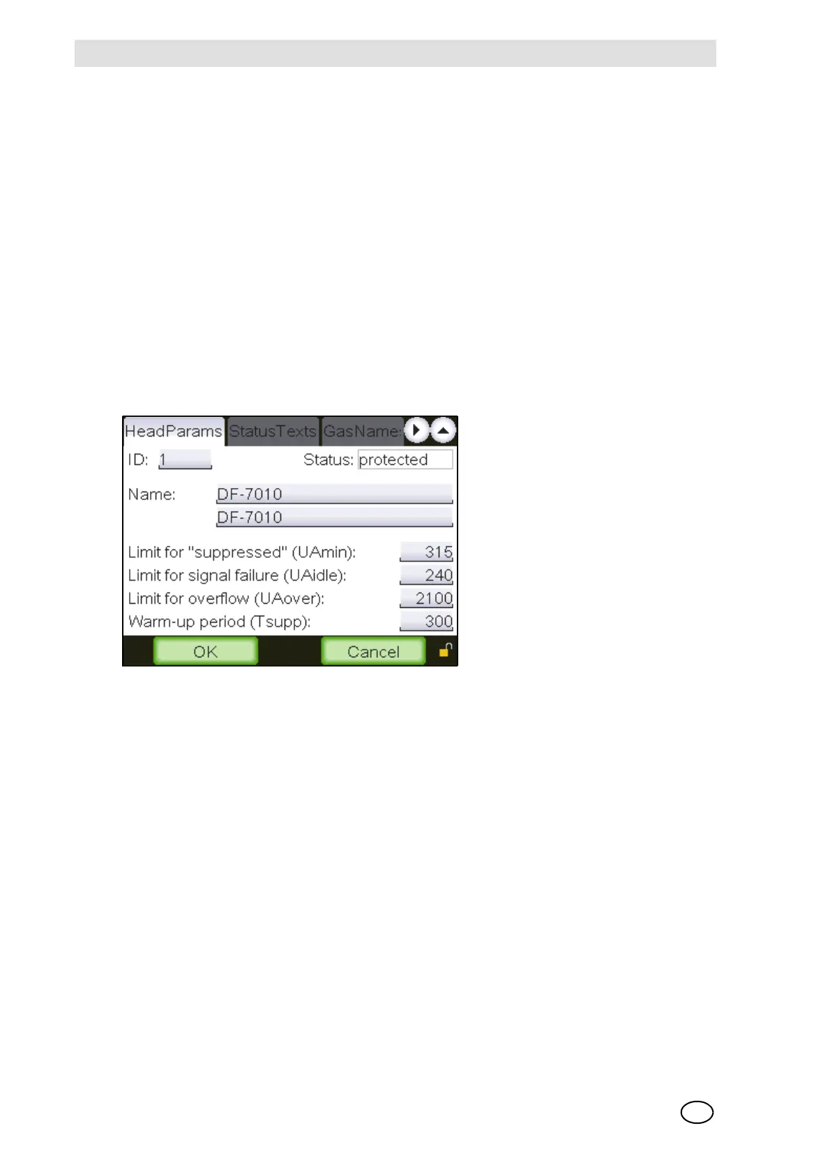
Head parameters
Fig. 20 “Head parameter”
This window displays the significant parameters of the remote sensing heads. During normal op-
eration the SUPREMATouch software permanently checks the detector output signal sent by to
the SUPREMATouch. In case the detector output signal falls below UA
min
an inhibit indication,
and below UA
idle
a fault indication will be set for this measuring point. In case the detector output
signal exceeds UAover an overflow will be indicated. Data fields that are not used for a specific
remote sensing head are empty.
It is possible to enter user specific data for some active [4…20 mA signal] remote sensing heads.
For this purpose, the following fields can be changed: Name [English and local language], UA
min
,
UA
idle
, UA
over
and T
supp
. The “ID” of modifiable remote sensing heads begins with the value
“10000” and their status is displayed as “changeable”.
The functions of the individual window elements are described below:
ID [Remote sensing head ID]
Field type: Selection
A remote sensing head can be selected in this field by means of its ID