Calibrating an Extensometer
Model 493.02 Controller Service
Calibration
189
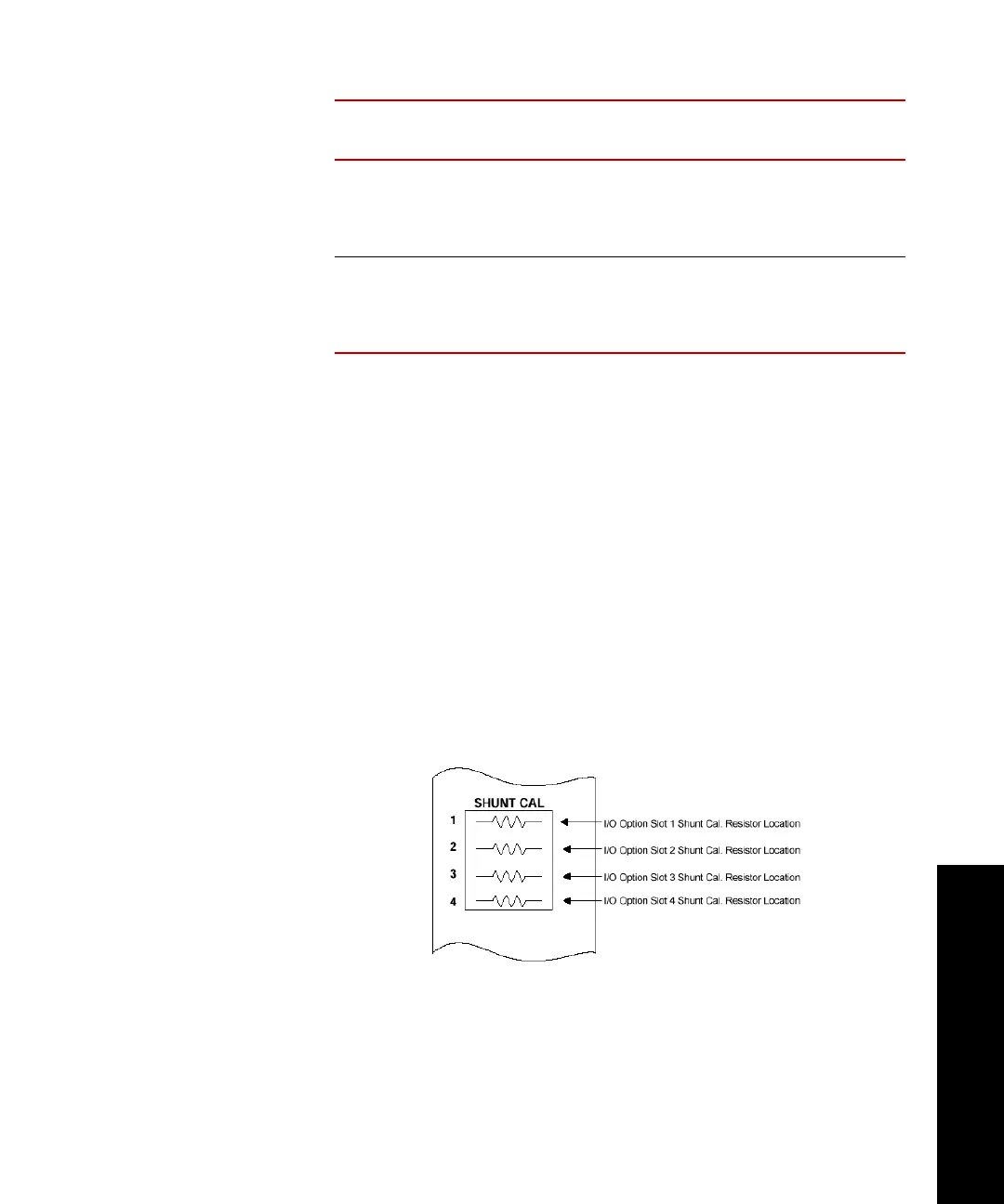
5. Install the shunt calibration resistor as follows:
A. Select the appropriate shunt calibration resistor.
B. Bend the resistor leads 90º for a 0.3 inch separation.
C. Cut the resistor leads 0.12 inch from the bend.
D. Insert the resistor into the connector solder cups and solder.
E. Complete and attach a shunt calibration label as specified on
the 493.40/41 Carrier I/O Shunt Calibration Kit (MTS PN 100-
028-185).
F. Install the shunt cal resistor/connector assembly into the
appropriate slot of the SHUNT CAL connector on the front
panel of the appropriate I/O Carrier Module.
700 Ω 2 mV/V 100%
50%
20%
10%
100 k
200 k
499 k
1000 k
700 Ω 1 mV/V 100%
50%
20%
10%
200 k
402 k
1000 k
2000 k
BRIDGE
R
ESISTANCE SENSITIVITY
RANGE
(% F
ULL SCALE)
R
ESISTOR
V
ALUE
 Loading...