MP7505 Series User Manual
User Interface
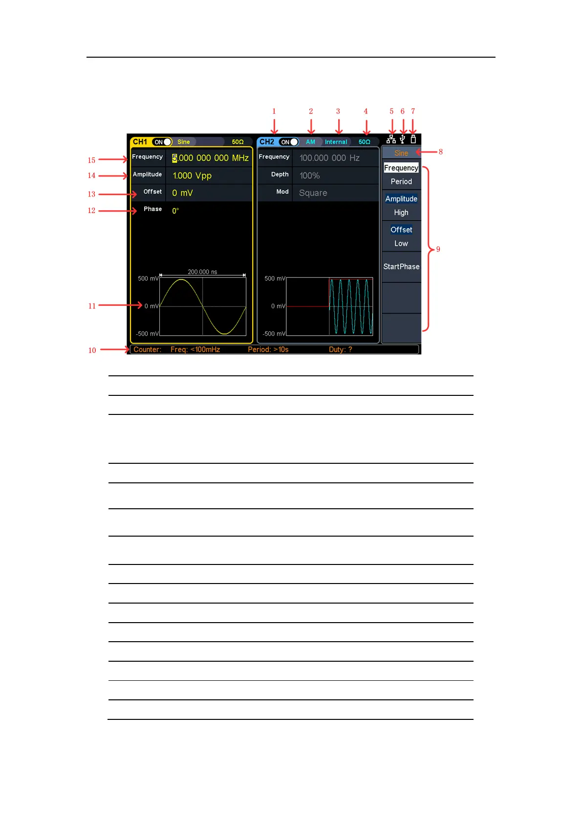
Figure 4-3: User Interface
Display channel name and channel switch status
Current waveform or current mode
Internal: Internal modulation or internal trigger source
External: External modulation or external trigger source
Manual: Manual trigger source
Load, High Z indicates high resistance
This indicator is lit when the network is connected through the LAN
interface.
Lights up the indicator when connected to the USB Host via the USB
DEVICE interface.
When the instrument detects the USB flash drive, it lights up the
indicator.
Current menu name
Current waveform or mode setting menu
Counter brief information showing frequency value, period value and
11
Display current waveform
Start phase
Offset / low level, depending on the right highlit menu item
Amplitude / high level, depending on the right highlit menu item
Frequency/cycle, depending on the highlit menu item on the right