MP7505 Series User Manual
AM
Sinusoidal segmented AM wave
FM
Sinusoidal segmented FM wave
PM
Sinusoidal segmented PM wave
PWM
Pulse width segmented PWM wave
64n/1024 Order adjustment (n is an integer, the range is 0 - 16)
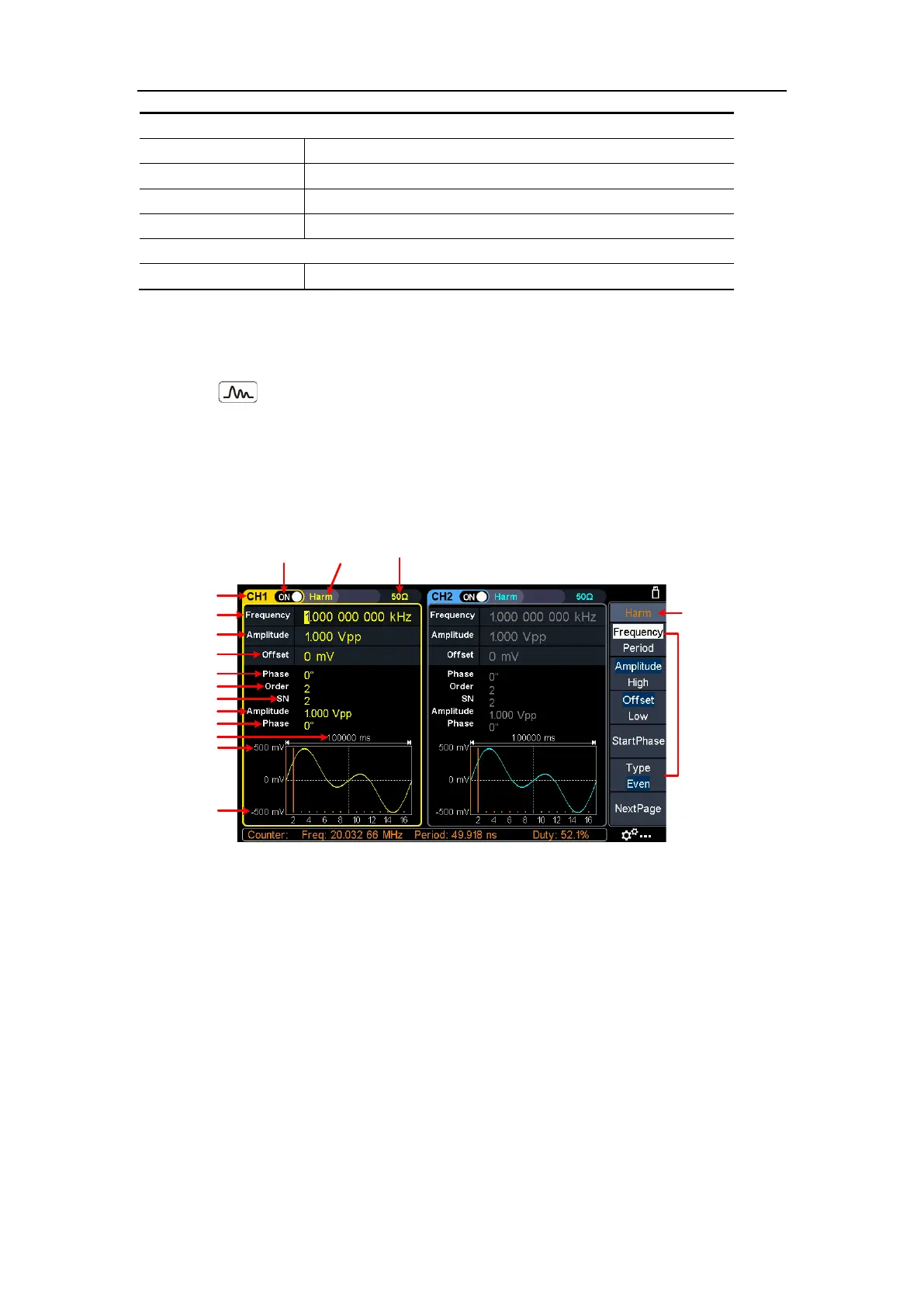
Output Harmonic Wave
Press the Harmonic wave button, the screen displays the user interface of the
harmonic wave. The Harmonic waveform parameters can be set by operating the
Harmonic setting menu on the right.
The harmonic wave menu includes: Frequency/Period, Amplitude/High Level,
Offset/Low Level, Start Phase, Harmonic Type, Harmonic Order, Sequence Number,
Harmonic Amplitude, Harmonic Phase.
Channel
Parameter 4
Current signal
Period
High Level
Low Level
Parameter 1
Parameter 2
Parameter 3
Parameter 5
Setting menu of
Harmonic signal
Current
signal
Load
Output
switch
Parameter 6
Parameter 7
Parameter 8
Figure 5-10: Harmonic wave user interface
Harmonic wave function overview
According to Fourier transform theory, time domain waveform is the superposition of
a series of sine waveforms, expressed by the following equation:
f
(t)
=
A
1
sin(2
π
f
1
t
+
ϕ
1
)
+
A
2
sin(2
π
f
2
t
+
ϕ
2
)
+
A
3
sin(2
π
f
3
t
+
ϕ
3
)
+
......
Generally, the component of frequency
f
1
is called the fundamental wave,
f
1
is the
fundamental waveform frequency,
A
1
is the fundamental waveform amplitude, and
ϕ
1
is the fundamental waveform phase. The frequencies of other component are all
integral multiples of the fundamental waveform frequency, which is called harmonic.
A component whose frequency is an odd multiple of the fundamental frequency is
called an odd harmonic, and a component whose frequency is an even multiple of