Underground Corrosion Control 3:14
CP 1 – Cathodic Protection Tester Course Manual
© NACE International, 2000
02/01/05
• as above with a test box installed between the anode and the structure.
The test box may contain a resistor for control of current flow or a shunt
to measure current output.
• as bracelets clamped around a pipe and connected to it with a welded
pigtail connection.
• by means of a steel rod or strap cast in the anode and then welded to the
structure.
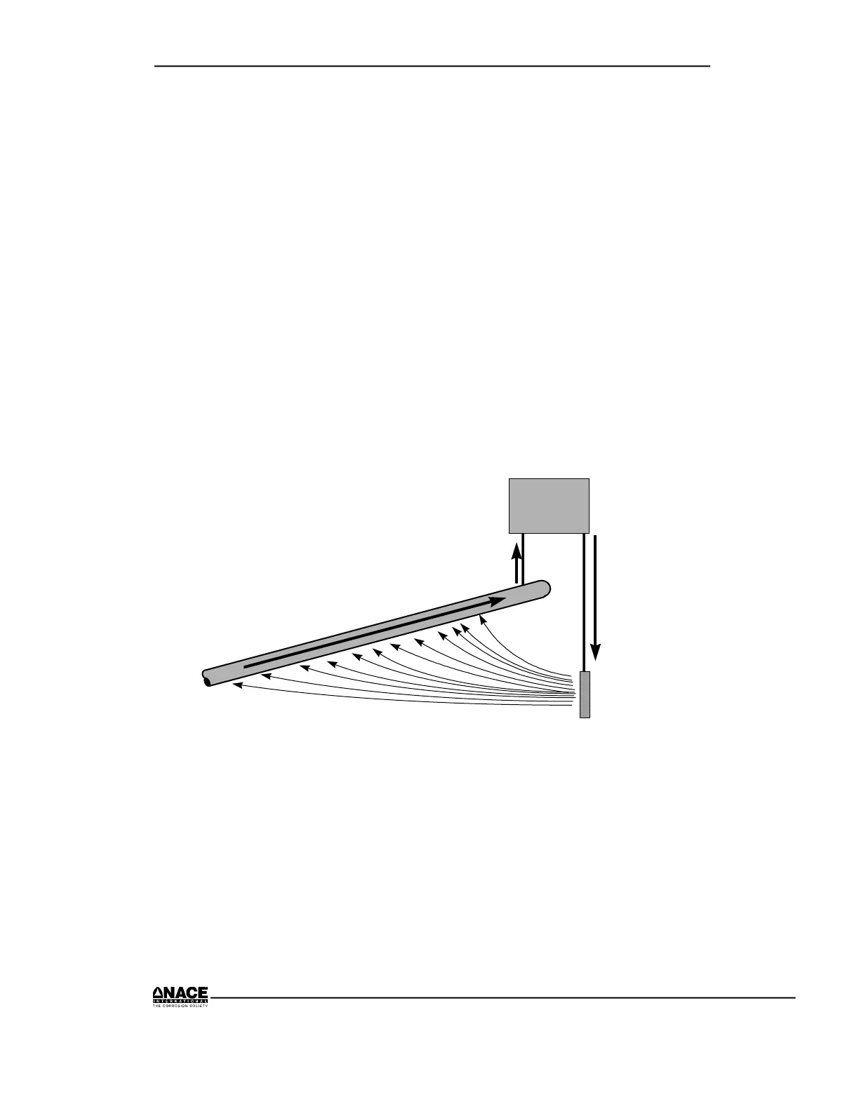
Impressed Current Systems
An impressed current system consists of an external power source and
anodes. The external power source forces current to flow from the anode to
the structure through the electrolyte. The anodes used in an impressed current
system are usually constructed of a relatively inert material. A typical
installation is shown in Figure 3.4.
ANODE
S
T
R
U
C
T
U
R
E
C
U
R
R
E
N
T
CURRENT
Power
Source
+
-
CURRENT
Figure 3.4 Typical Impressed Current Cathodic Protection
Anodes
Materials that have been used as impressed current anodes include:
• Graphite (carbon)
• High-silicon, chromium, cast iron
• Platinum-coated titanium and niobium
• Aluminum
• Magnetite