Installing C.P. Components 8:10
CP 1 – Cathodic Protection Tester Course Manual
© NACE International, 2000
07/01/04
Wherever possible, isolating joints should be installed above grade. Where
one must be buried, a test station should be installed with wires on either
side of the joint. The purpose of the test station is to enable one to
determine the effectiveness of the joint.
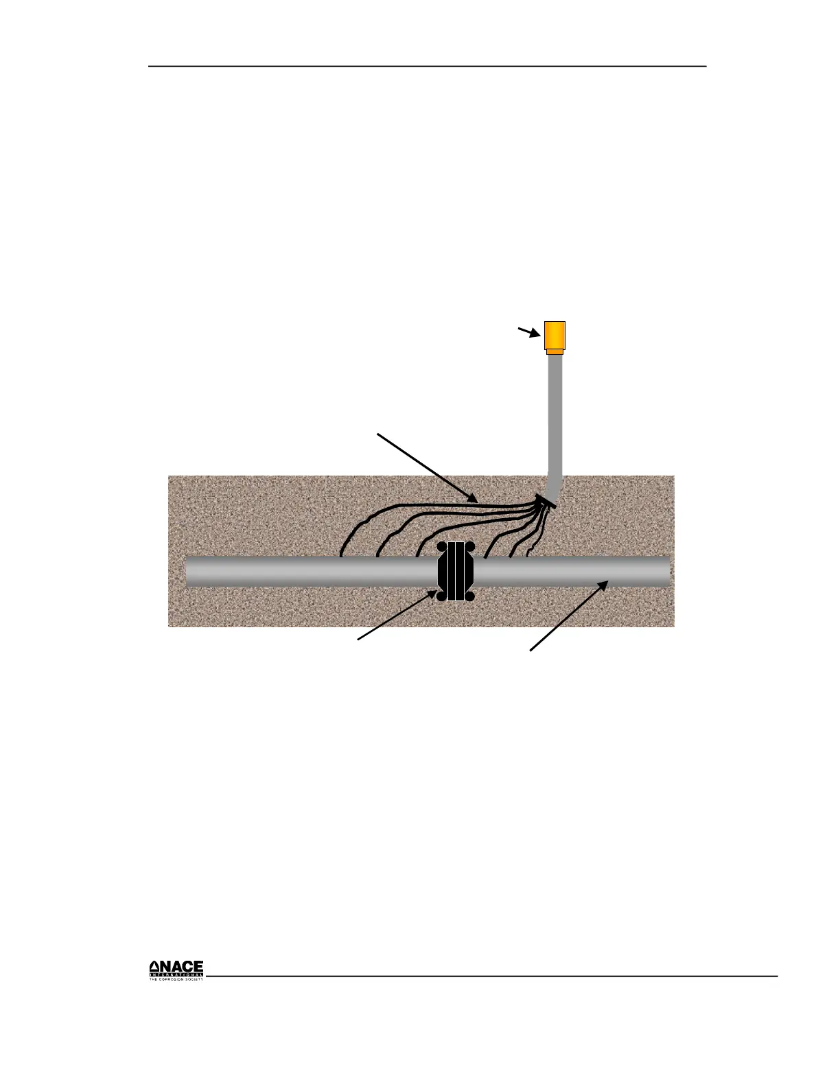
A typical isolating joint test station is shown in Figure 8.10. Note that
different colored wires are used on either side of the joint. This is important
so that you can tell which side of the joint is being tested. As with other test
stations containing wires of different colors, it is important that the wires
are placed as shown on the design drawings.
Pipeline
Isolating Joint
Test Station
Typically No. 12 AWG
Test Wires & No. 8
AWG Wire for
Bonding if Needed
Figure 8.10 Isolation Joint Test Station
Mitigation Bond
Coupons
Coupon test stations may contain one or both of two types of coupons–
polarization coupons and electric resistance “smart” probes. Polarization
coupons are made of the same material as the structure. They are located
near the structure and connected to it through the test station head. One
purpose is to allow for “instant off” potential measurements without having
to interrupt the cathodic protection rectifier. Another is to measure the
protective current density on a holiday of known size.
 Loading...