Basic Electricity 1:11
CP 1 – Cathodic Protection Tester Course Manual
© NACE International, 2000
02/01/05
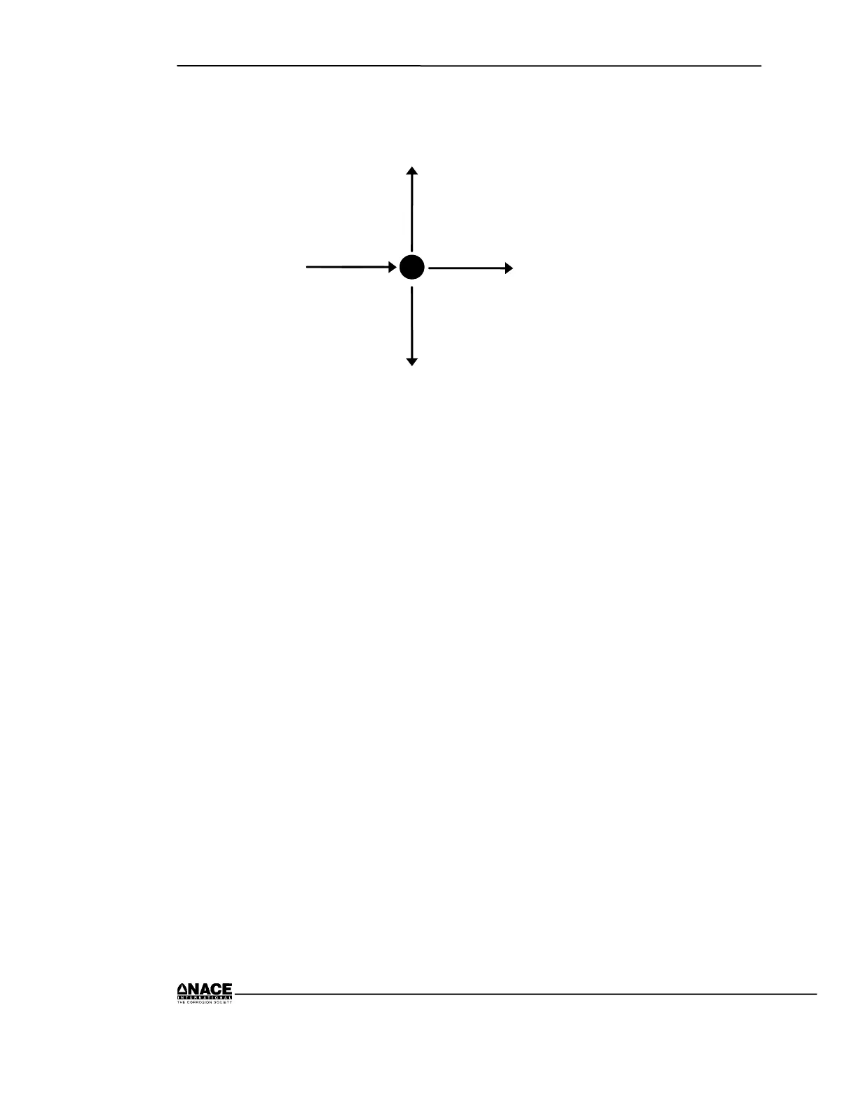
For example, in Figure 1.5:
Current in (6 A) = Current out (3 + 2 + 1 A)
6 A 3 A
1 A
2 A
Figure 1.5 Kirchhoff’s Current Law
Series Circuit
In a series circuit (Figure 1.6), the same current flows in an
individual, consecutive, and continuous path from the source of
voltage through the various loads and back to the source.
• The current is the same everywhere.
• The voltage drops may all be different depending on the value of
each resistance, but the sum of the voltage drops (E
T
) must add
up to the voltage of the source (an example of Kirchhoff's
Voltage Law).
• The total resistance (R
T
) of a series circuit equals the sum of the
individual resistances.
In cathodic protection work, we are concerned with series circuits,
for example, in the length of cables running out to groundbeds. The
longer the wire (a series circuit), the higher the resistance and the
lower the current for a given voltage. The resistance between a
single galvanic anode and a structure also represents a series circuit.