Troubleshooting 9:6
CP 1 – Cathodic Protection Tester Course Manual
© NACE International, 2000
07/01/04
when two structures are electrically isolated from each other by a fitting or
a casing spacer, there is still a parallel resistance through the electrolyte.
The ohmmeter cannot distinguish between the resistance of the fitting and
that through the electrolyte. More important, however, is the fact that there
is nearly always a voltage difference between two isolated structures. This
voltage affects the total voltage of the measuring circuit and creates
appreciable errors. A high resistance may be indicated with the leads
connected one way and a low resistance with the leads reversed.
Isolating Joint Shorts
Buried isolating joints (flanges, couplings, monolithic joints, etc.) should
have test wires attached on either side of them to facilitate testing the
effectiveness of the joint. If no test wires are in place, testing can be
conducted if contact can be made to the pipe on either side of the joint.
Testing is similar to that for casings. If the joint is effective, the pipe-to-soil
potential on either side of it should differ by usually 0.250 volt to 1.000 volt
or more.
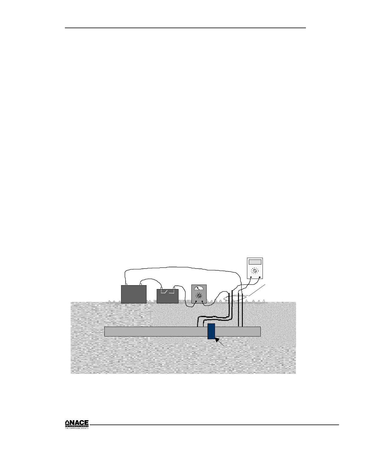
If the pipe on either side of the joint has cathodic protection, there may be
little or no difference between the readings. In this case, current pick-up or
resistance testing (as described above under “Casing Shorts”) will indicate
the effectiveness of the joint. Figure 9.5 illustrates resistance testing.
Wires
must be
color
coded
0.17
mV
+
_
PIPELINE
Power
Source
+
_
Current
Interrupter
+
_
AMPS
VOLTS
ISOLATING FITTING
Figure 9.5 Resistance Test Set-Up for an Isolating Joint
 Loading...