Installing C.P. Components 8:28
CP 1 – Cathodic Protection Tester Course Manual
© NACE International, 2000
07/01/04
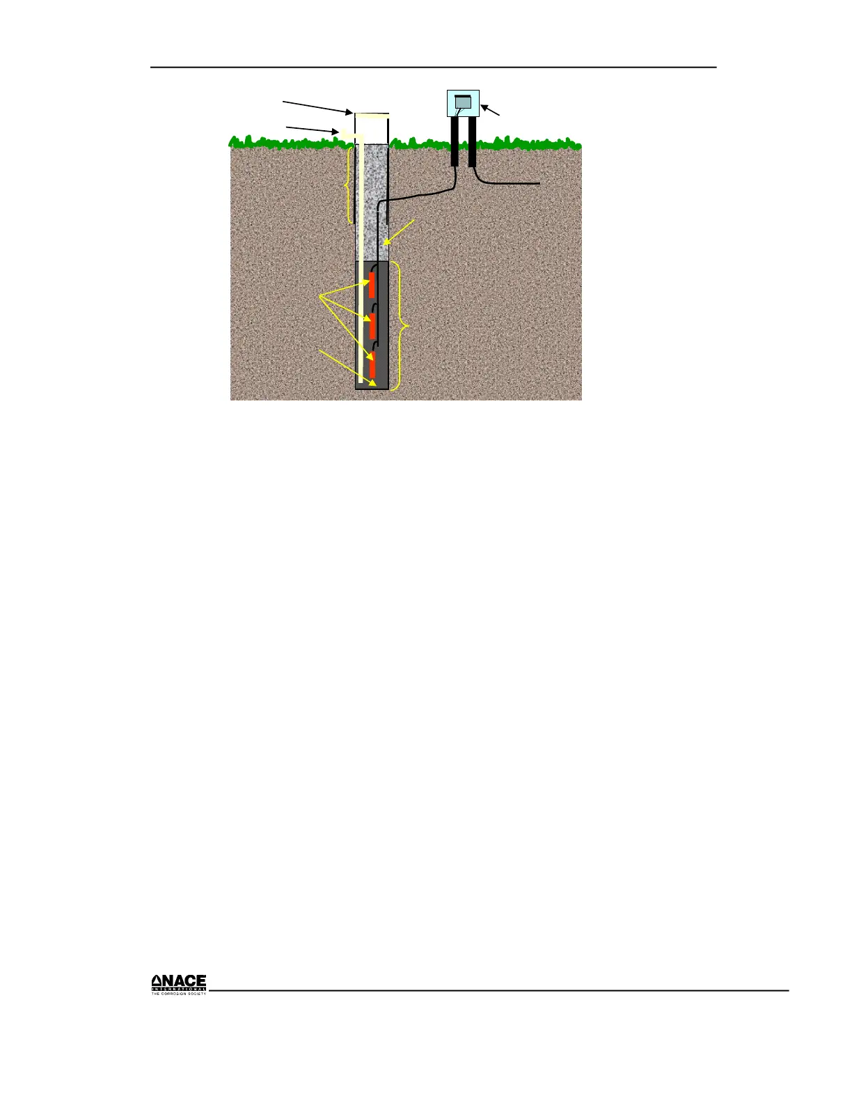
Active Anode Area
To Rectifier
Shunt Box
Anodes
Coke Breeze
Well Cap
Vent
Casing
Gravel
NOTE: Sealing
may be required
by state or local
codes
Figure 8.24 Deep Anode Installation
Negative Circuit
The negative or return circuit is the cabling from the structure to the
rectifier. Be certain to follow the design specifications and drawings during
installation.
Some cathodic protection designs have more than one negative circuit. This
usually occurs when two or more facilities are being protected by a single
rectifier. In order to control the current flowing to each structure, negative
cables may be run to a junction box in which resistors can be placed.
Follow wiring diagrams carefully to ensure the negative circuits are
connected to the correct terminals in the junction box.
Be careful not to damage the insulation on the negative cable. Damage to
the insulation is not as critical as it is on the positive cable, because the
negative cable is on the cathodic side of the circuit. Still, precautions need
to be taken in handling the negative cable.
The connection between the negative cable and the structure can be made
by thermite welding or by a mechanical connection. Refer to the section on
“Wire Attachment” for procedures and precautions.
Negative cables may be fairly heavy, ranging typically from No. 6 AWG to
No. 2/0 AWG or larger. This size wire is too large to connect to a pipeline
 Loading...