Basic Chemistry and Basic Corrosion Theory 2:13
CP 1 – Cathodic Protection Tester Course Manual
© NACE International, 2000
02/01/05
There are several voltage measurements commonly made in cathodic
protection surveys:
• driving voltage of a galvanic anode system
• rectifier voltage output
• structure-to-electrolyte potential
• voltage drop across a pipe span
• voltage across a current shunt
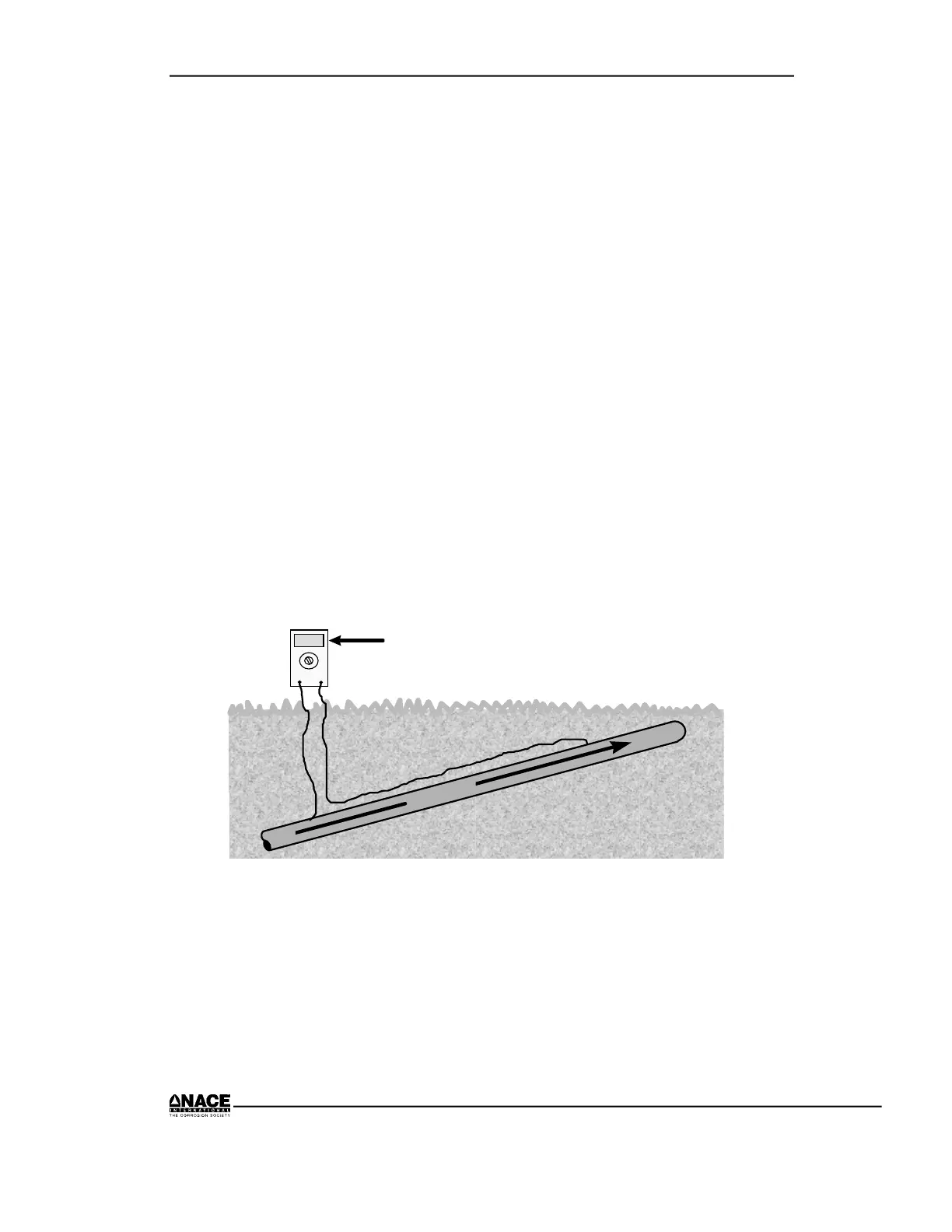
A voltage measurement, like any measurement, should be taken with an
anticipated value in mind including the magnitude, sign, and units to
prevent mistakes in meter connections, misreading the meter, or
overlooking problems with the system.
Polarity Sign
Most digital meters will display a negative sign for a negative reading and
no sign for a positive reading. When a voltmeter is connected across a
metallic element, such as a wire or pipeline with external current flow, the
voltage display is positive when the positive terminal of the voltmeter is
upstream of the current flow as illustrated in Figure 2.12.
C
u
r
r
e
n
t
20
MV
+
_
Voltage measurement is positive
Figure 2.12 Current Direction
When measuring the voltage difference of dissimilar metals, the sign is
positive when the positive terminal of the voltmeter is connected to the
more noble metal as shown in Figure 2.13.