Technical Manual N5 (CANopen)
3 Technical details and pin assignment
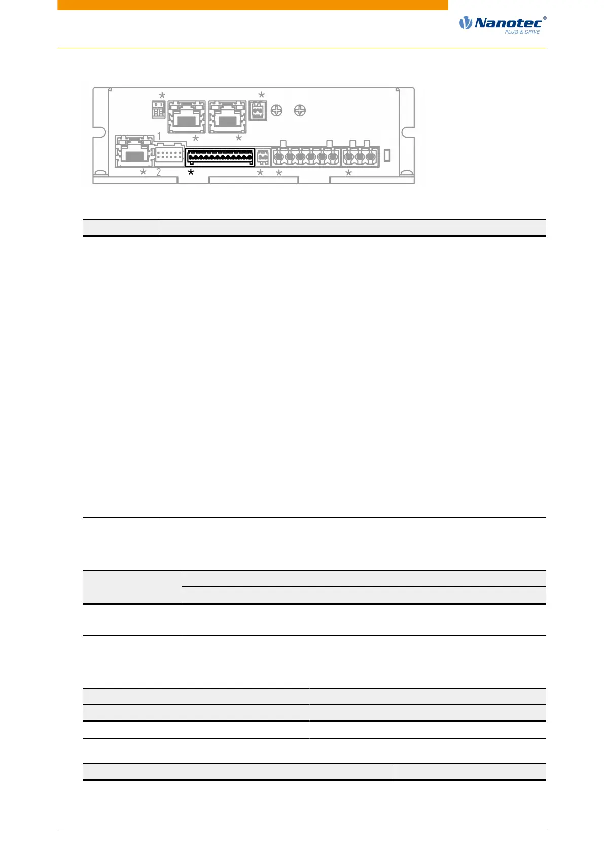
X7
X5X1 X2 X3 X4 X6
L1
X6
S1
X8X9S3
S2
PIN Function Note
1 GND
2 Input 1 5 V / 24 V digital input, switchable by means of software with object
3240
h
, max. 1 MHz
3 Input 2 5 V / 24 V digital input, switchable by means of software with object
3240, max. 1 MHz
4 Input 3 5 V / 24 V digital input, switchable by means of software with object
3240, max. 1 MHz, direction input in clock-direction mode
5 Input 4 5 V / 24 V digital input, switchable by means of software with object
3240, max. 1 MHz, clock input in clock-direction mode
6 Input 5 Digital input 5 V to 24 V, not switchable by means of software, max.
1 MHz
7 Input 6 Digital input 5 V to 24 V, not switchable by means of software, max.
1 MHz
8 Analog input 1 -10 V…+10 V or 0…20 mA, switchable by means of software with
object 3221
h
9 Analog input 2 -10 V…+10 V or 0…20 mA, switchable by means of software with
object 3221
h
10 Output 1 Digital output, open drain, max. 24 V / 0.5 A
11 Output 2 Digital output, open drain, max. 24 V / 0.5 A
12 Shielding Shielding
The following switching thresholds apply for inputs 1 to 4:
Switching thresholdsMax. Voltage
Safe switch on Safe switch off
5 V > approx. 3 V < approx. 1 V
24 V > approx. 16 V < approx. 7 V
The following switching thresholds apply for inputs 5 and 6 (wide-range inputs from 5-24 V):
Switching thresholds
On Off
> approx. 3 V < approx. 2 V
Connection data min max
Conductor cross section, rigid, min. 0.14 mm
2
0.5 mm
2
Version: 2.0.1 / FIR-v1650 22


 To Next Page