Technical Manual N5 (CANopen)
3 Technical details and pin assignment
PIN Function
(stepper
motor)
Function
(BLDC motor)
Note
1 Shielding Shielding Shielding
2 A U
3 A\ V
4 B W
5 B\ Not used
6 Shielding Shielding Shielding
Connection data min max
Conductor cross section, rigid 0.2 mm
2
2.5 mm
2
Conductor cross section, flexible 0.2 mm
2
2.5 mm
2
Conductor cross section, flexible, min. Wire-end sleeve without
plastic sleeve
0.25 mm
2
2.5 mm
2
Conductor cross section, flexible, min. Wire-end sleeve min. Plastic
sleeve
0.25 mm
2
1.5 mm
2
Conductor cross section, AWG 24 12
2 conductors of the same cross section, flexible, min. TWIN-AEH
with plastic sleeve
0.5 mm
2
1.5 mm
2
AWG acc. to UL/CUL 26 12
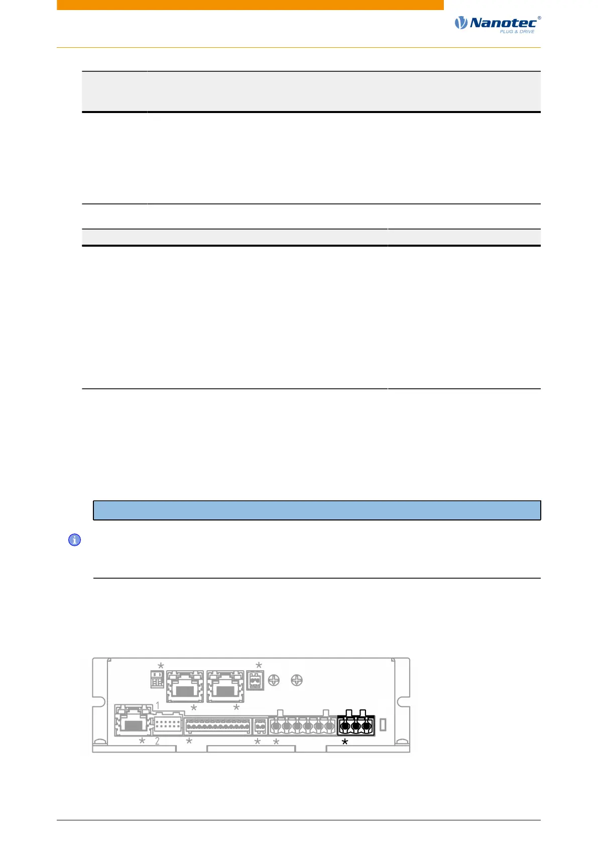
3.6.7 Connector X6 – voltage supply
Voltage source
The operating or supply voltage supplies a battery, a transformer with rectification and filtering, or a
switching power supply.
Note
• EMC: For a DC power supply line longer than 30 m or when using the motor on a DC bus, additional
interference-suppression and protection measures are necessary.
• An EMI filter is to be inserted in the DC supply line as close as possible to the controller/motor.
• Long data or supply lines are to be routed through ferrites.
Connections
Pin 1 is marked with an asterisk "*".
X7
X5X1 X2 X3 X4 X6
L1
X6
S1
X8X9S3
S2
Version: 2.0.1 / FIR-v1650 24


 To Next Page