Technical Manual N5 (CANopen)
3 Technical details and pin assignment
• Controller communication
• Encoder
Note
The windings of the motor are not supplied by the logic supply.
In this case, a voltage of 24 V DC must be connected to X7. With a 24 V encoder, object 2059
h
must be set to the value "1". In the case of a 5 V encoder, object 2059
h
is to be set to the value "0".
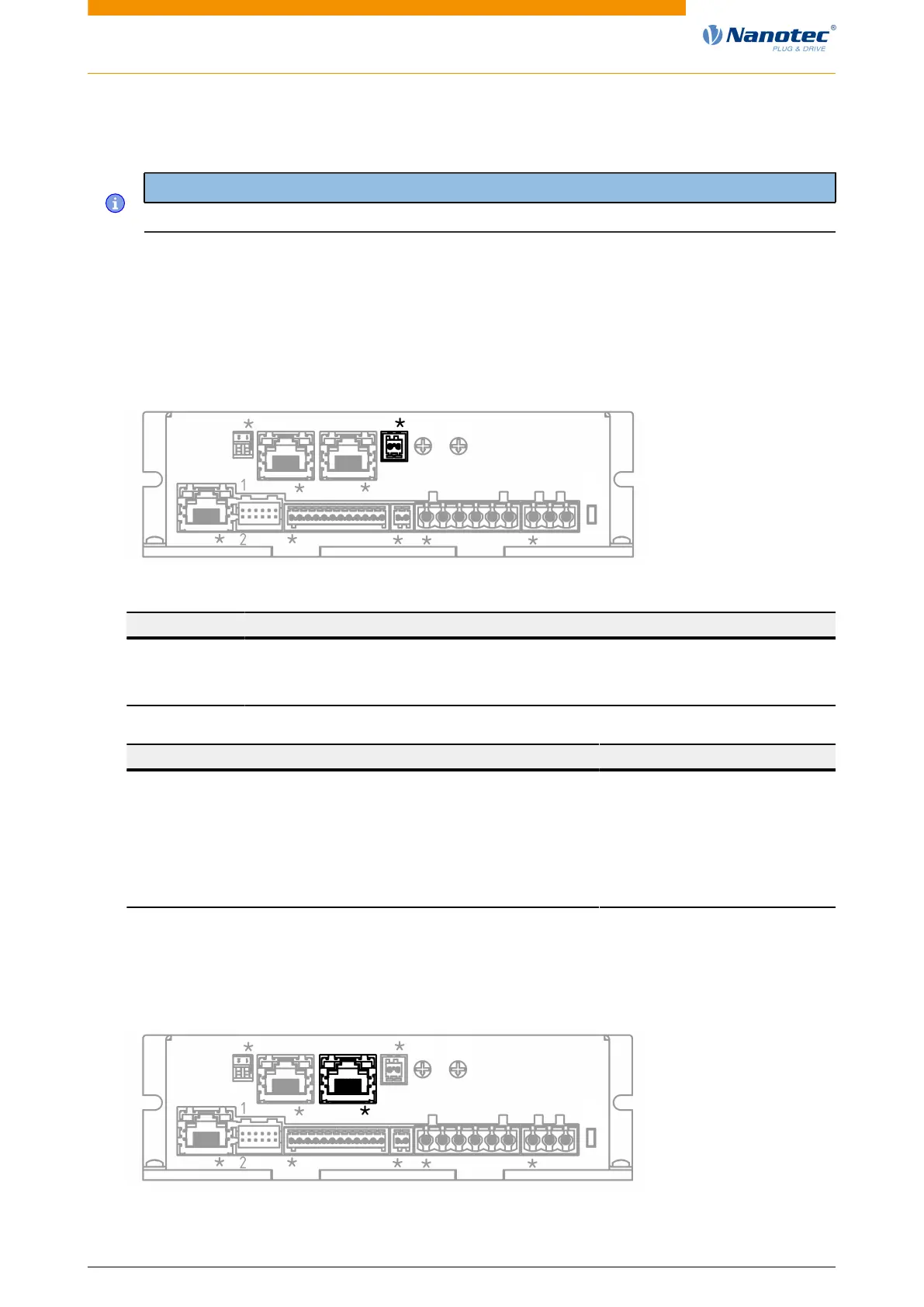
Connection
Pin 1 is marked with an asterisk "*".
X7
X5X1 X2 X3 X4 X6
L1
X6
S1
X8X9S3
S2
PIN Function Note
1 +UB Logic/
encoder
+24 V DC, supply voltage for logic and encoder/Hall sensor
2 GND
Connection data min max
Conductor cross section, rigid, min. 0.14 mm
2
0.5 mm
2
Conductor cross section, flexible, min. 0.14 mm
2
0.5 mm
2
Conductor cross section, flexible, min. Wire-end sleeve without
plastic sleeve, min.
0.25 mm
2
0.5 mm
2
Conductor cross section, min. AWG 26 20
Min. AWG acc. to UL/CUL 28 20
3.6.9 Connector X8 – CANopen IN
Pin 1 is marked with an asterisk "*".
X7
X5X1 X2 X3 X4 X6
L1
X6
S1
X8X9S3
S2
Version: 2.0.1 / FIR-v1650 26


 To Next Page