Technical Manual N5 (CANopen)
3 Technical details and pin assignment
PIN Function Note
1 CAN+
2 CAN-
3 CAN GND Internally connected to PIN 7
4 n.c.
5 n.c.
6 CAN_SHLD Connection for the shielding
7 GND Internally connected to PIN 3
8 +UB Logic +24 V DC, input voltage, current consumption approx. 60 mA
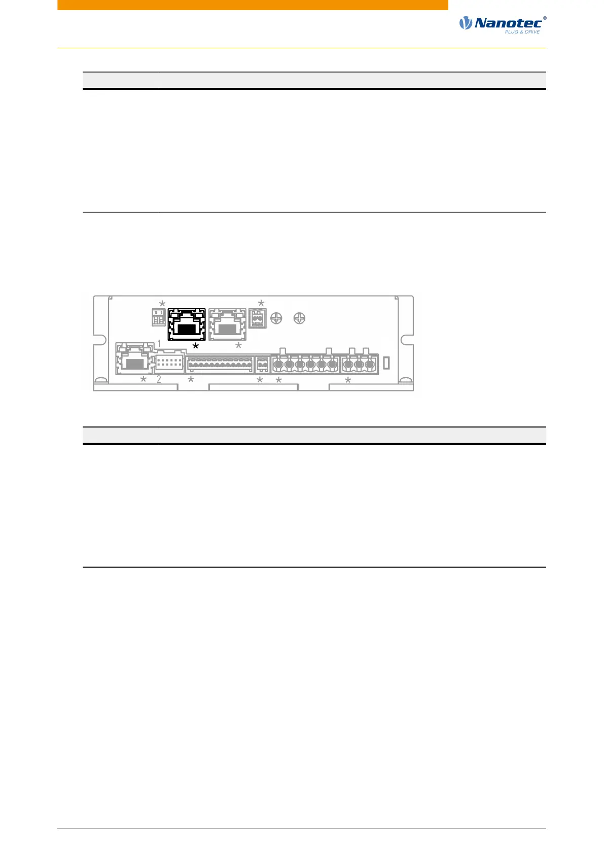
3.6.10 Connector X9 – CANopen OUT
Pin 1 is marked with an asterisk "*".
X7
X5X1 X2 X3 X4 X6
L1
X6
S1
X8X9S3
S2
PIN Function Note
1 CAN+
2 CAN-
3 CAN GND Internally connected to PIN 7
4 n.c.
5 n.c.
6 CAN_SHLD Connection for the shielding
7 GND Internally connected to PIN 3
8 +UB Logic +24 V DC, input voltage, current consumption approx. 60 mA
3.6.11 Switch S1 – CANopen node-ID and baud rate
Hex coding switch for setting the CANopen node-ID and baud rate. See chapter Setting node-ID and
baud rate.
The value of this switch is multiplied by 16 and added to the value of switch S2; this switch thereby sets
the 16s place.
Version: 2.0.1 / FIR-v1650 27


 To Next Page