AVIOR-24S ™ CHAPTER 1
Starter Kit
19
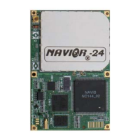
NAVIOR-24S ™ Revision V1.00 20.05.2008
The interface motherboard includes a 7 to 15 VDC switching power supply which provides
regulated +3.3 VDC power to the receiver, and contains circuitry which provides two RS-232
interface ports and RS-485 port for 1PPS. A 3.0V lithium backup battery enables quick warm starts.
Pin 9 of the Port 2 DB-9F connector on the front of the interface unit, two LED indicators for 1PPS
and Power, RESET bottom are placed on the front panel.
The Starter Kit includes AC/DC converter for powering the module from AC wall socket. The
metal enclosure (see Figure I-2, Figure I-3) provides two DB9 and one DB15 interface port
connectors, an antenna connector, two LED indicators and a power connector.
Port “COM 1” and Port “СОМ 2“ are used for serial I/O and are placed on the front panel.
Port “COM 3”, antenna connection TNC socket, power connector and bonding point are placed on
the rear panel.
The mounting plate is secured to the metal enclosure with four screws. Figure I-2 Starter Kit front
panel view illustrates the Starter Kit interface unit.