AVIOR-24S ™ CHAPTER 1
Starter Kit
18
NAVIOR-24S ™ Revision V1.00 20.05.2008
Starter Kit Interface Unit
The Starter Kit interface unit consists of a NAVIOR-24S GPS/GLONASS module attached to an
interface motherboard, housed in a sturdy metal enclosure. This packaging simplifies testing and
evaluation of the module by providing two RS-232 serial interfaces which are compatible with most
PC communication ports. Power (7-15 VDC) is supplied through the power connector on the front
of the interface unit. The motherboard features a switching power supply which converts this
voltage input to the 3.3 volts required by the module and antenna. The two DB9 connectors allow
for easy connection to a PC serial port using the serial interface cable provided in the Starter Kit.
The metal enclosure protects the module and the motherboard for testing outside of the laboratory
environment.
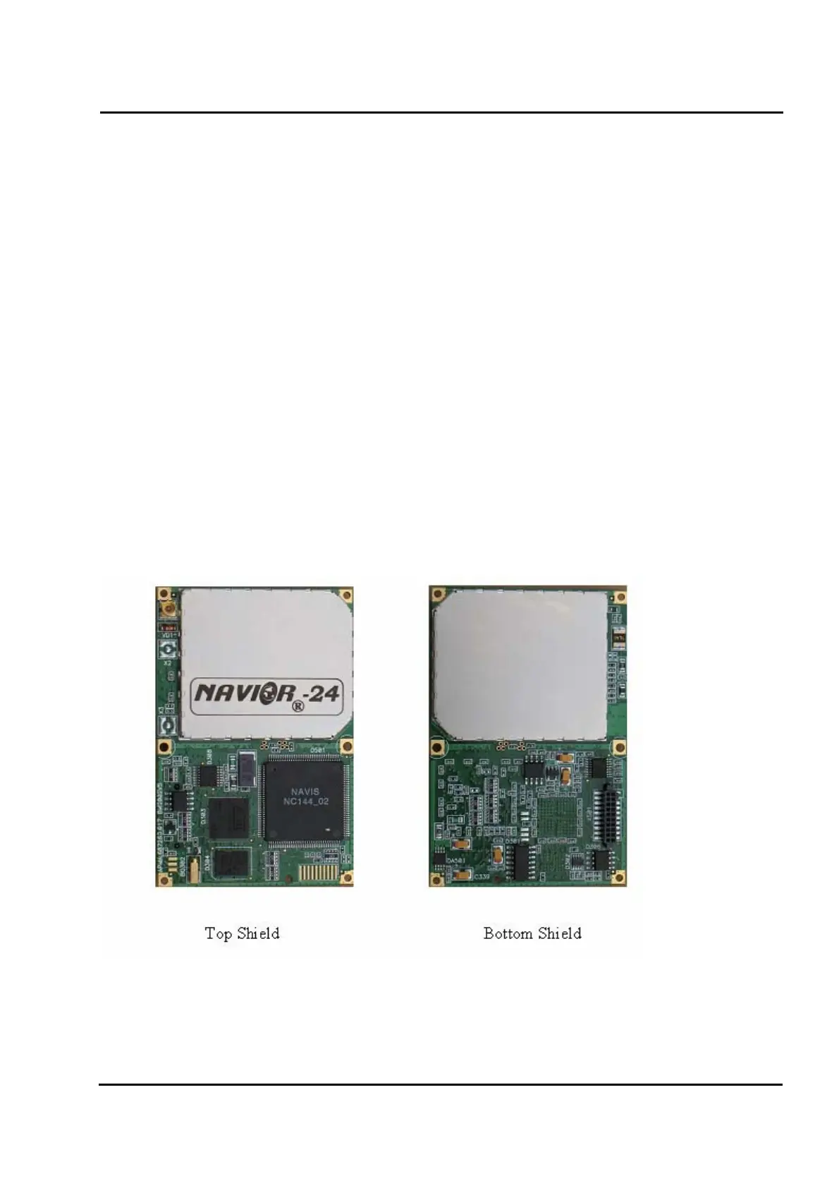
The RF part of the NAVIOR-24S GPS/GLONASS receiver is encased in a sturdy metal enclosure.
The dimensions of the receiver in this enclosure are 50 mm (W) x 75 mm (L) x 12 mm (H). A
straight-in, panel-mount RF connector (X1) supports the GPS/GLONASS antenna connection. The
center conductor of the coaxial connector also supplies +3.3 VDC for the Low Noise Amplifier of
the active antenna. 20-pin (2x10) connector, (X2) supports two serial interfaces (CMOS level),
pulse-per-second (PPS) signal (CMOS level), input power (+3.3 VDC), antenna power
(+3.3…+5.0) VDC, back-up power (2,0…3,0 VDC),. Figure I-1 illustrates the NAVIOR-24S
GPS/GLONASS receiver module.
Figure I-1 NAVIOR-24S GPS/GLONASS receiver module