AVIOR-24S ™ CHAPTER 1
Starter Kit
22
NAVIOR-24S ™ Revision V1.00 20.05.2008
Power
NAVIOR-24S GPS/GLONASS receiver is designed for embedded applications and requires a
regulated +3.3 VDC input (+3.20 to +3.45 VDC). The receiver, provided in the Starter Kit, is
installed on a motherboard, providing a DC power regulator which converts from 7 to 15 VDC
input to the regulated 3.3 VDC required by the receiver. Power can be applied to the interface unit
using one of two options: the DC power cable (see Table I-4) or the AC/DC power converter
(Figure I-4).
The DC power cable is ideal for bench-top or automotive testing environments. Pin 11, 12 power
contacts lead to a source of DC (positive) +7 to +15 VDC and pin 14, 15 power contacts lead to
ground (negative) -7 to -15 VDC). This connection supplies power to both of the receiver and
antenna.
Note – The DC power cable is not provided in the Starter Kit.
Note – Battery back-up power is provided by a factory installed 3.0V lithium battery on the
motherboard.
Warning – The Starter Kit interface unit must be bonded to a ground plane.
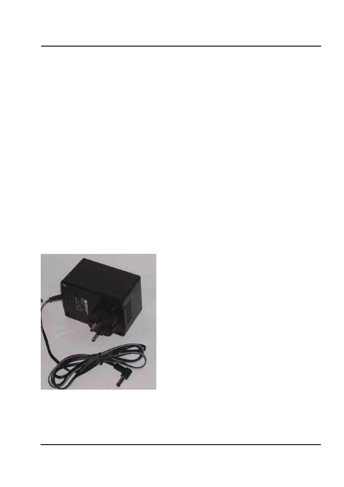
The AC/DC power converter may be used as an alternate power source for the interface unit. The
AC/DC power converter converts 220 VAC to a regulated 9 VDC, compatible with the interface
unit. The AC/DC power converter output cable is terminated with a DJK connector, compatible
with the power connector on the metal enclosure. The input connector is a standard DJK connector,
used on many desktop PCs.
Figure I-4 AC/DC Power Converter