Solution System 114Service Manual – SC500
Water Level Sensor Operation
The water level sensor (SW1) is positioned about half the height of the solution tank so as to provide the in-
formation to the electronic system on the level of water present in the tank (more than half, less than half).
Through this information the times of opening of the solenoid valve (EV1) and the detergent pump (M4) are
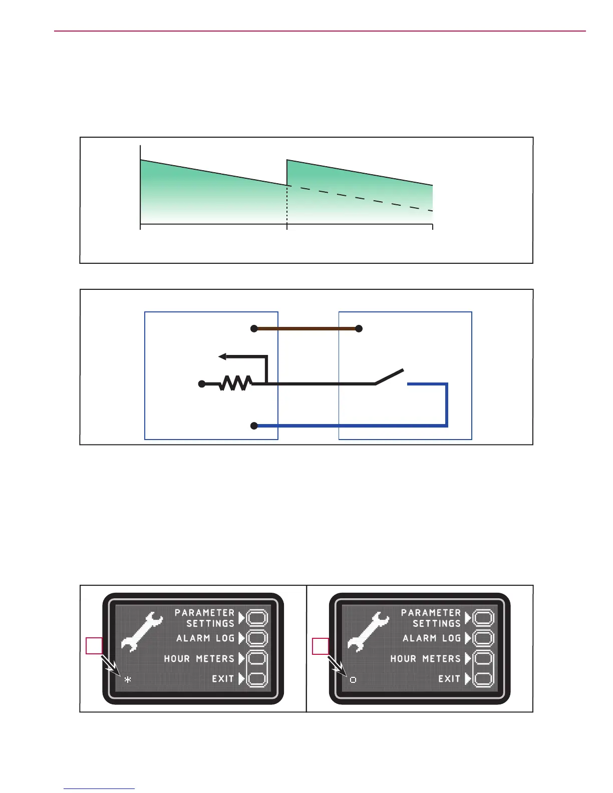
adjusted to maintain this ow more constant (Figure 10).
The water level sensor is capacitive with NPN output (output 0 Volt with water, oating without water).
Full ½Empty
Solution tank
With sensor
Without sensor
Solution ow
to the brush
(Litre/min)
Figura 10
J5.1
J5.2
J5.3
FUNCTION ELECTRONIC BOARD (EB1)
WATER LEVEL SENSOR (SW1)
24V(B+)
0V(B-)
Power Supply
Input
5V
Figura 11
Checking the Water Level Sensor Operation
1. Insert the Super User key (yellow) in place of the operator key (grey) to access the main screen (Figure
12) of the multifunction display.
2. With the solution tank more than half full, the symbol displayed is (A).
3. With the solution tank less than half full, the symbol displayed is (B).
Figure 12
A
B

 Loading...


