Wheel System, Traction 124Service Manual – SC500
Wheel System, Traction
Functional Description
Machine movement is provided by the gear motor unit (M3).
The gear motor unit (M3) also functions as the main support of the machine, and is composed of an electric
motor, the reduction unit with differential and the drive wheels.
The operator regulates the transfer speed, the working speed and reverse via the paddles, which are connected
directly to the speed potentiometer (RV1). Reversing is performed by pressing the back paddle.
The function board (EB1) checks that the paddles are not pressed when the machine is started; if they are, an
alarm is generated (see section “Function Board Alarm Codes” in the “Control System” chapter) and the drive
system is inhibited.
Once the paddles are returned to the rest position, the alarm will stop automatically (without the need to turn
the machine on and off).
When the paddles are pressed, the Function Board (EB1) supplies a voltage to the motor proportional to the
position of the paddles themselves. The acceleration ramps and maximum speed can be set via the correspond-
ing parameters (see section “Displaying and Modifying User Modiable Parameters” in the “Control System”
chapter).
Regulation of the maximum speed can be set with the buttons (hare / tortoise) on the Dashboard Instrument
Board (EB3).
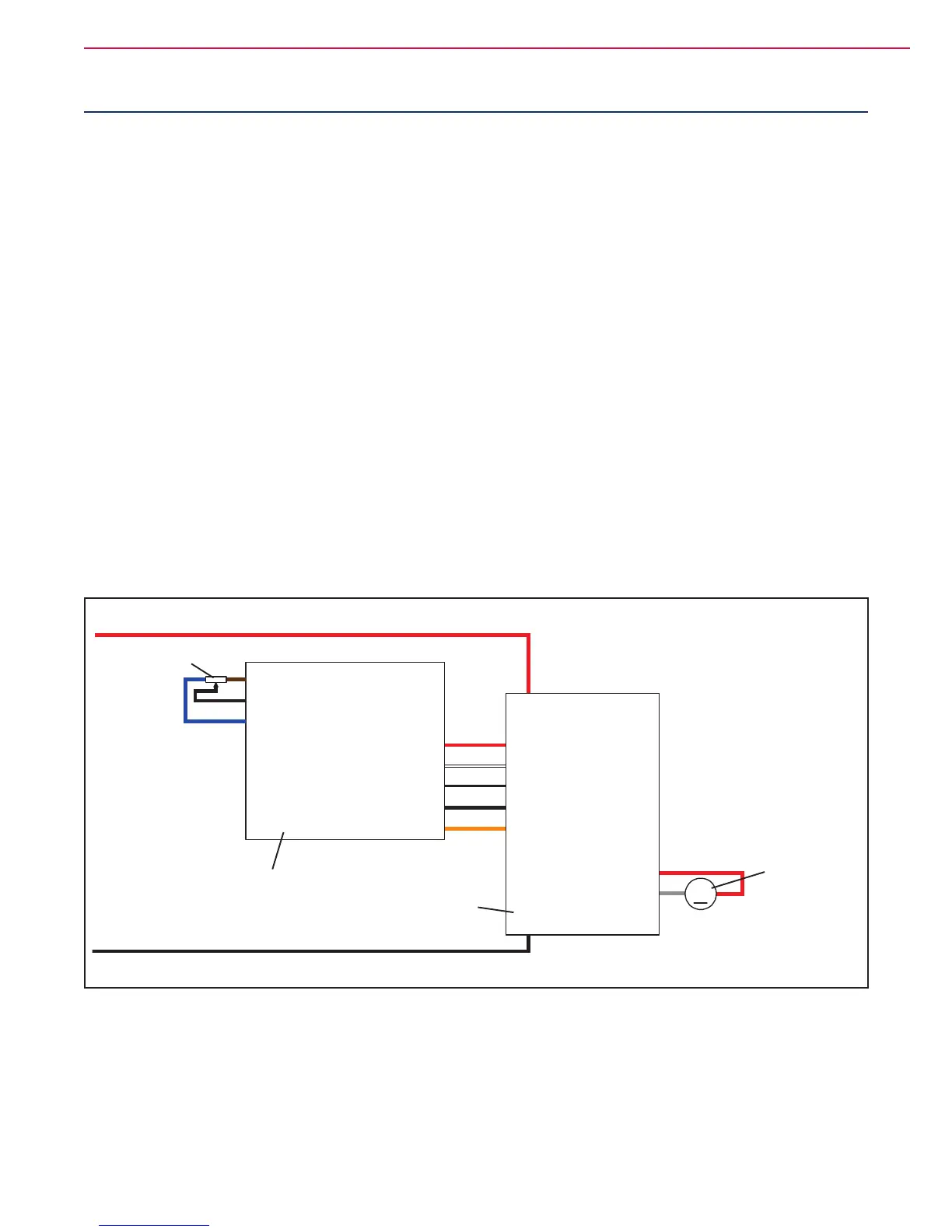
Wiring Diagram
M3
J1.5
J1.4
J1.3
J1.2
J1.1
J4.1
J4.2
J4.3
VR1 potentiometer power supply +
VR1 potentiometer return
VR1 potentiometer power supply -
M2
M1
Drive system motor -
Drive system motor +
J3.1
J3.2
J3.3
J3.4
J3.5
B-
B+
FUNCTION
ELECTRONIC
BOARD (EB1)
DISPLAY BOARD (EB2)
DRIVE SYSTEM
MOTOR (M3)
Dashboard power supply +
El. board power supply +
El. board power supply -
Dashboard serial +
Dashboard serial -
Dashboard power supply -
Return from key
Dashboard power supply +
Dashboard serial +
Dashboard serial -
Dashboard power supply -
Return from key
SPEED POTENTIOMETER
(RV1)
Figure 1

 Loading...


