Electrical System 58Service Manual – SC500
Electrical System
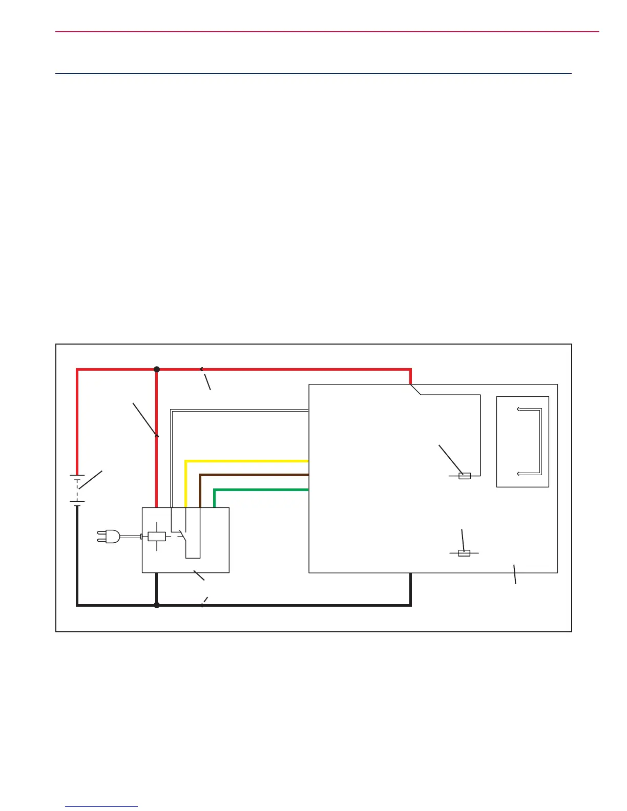
Functional Description
The batteries (2 x 12V) are connected together in se-
ries by the cables.
The battery charger (CH) is connected to the machine
by two connectors (C) (power connection to the batter-
ies) and C3 (4-way signal connection).
The grey and white cables (1 and 2 of connector C3) are
short circuited inside the battery charger CH when
this is not connected to the mains. If this connection is
not made, all machine functions are disabled.
If the optional battery charger has not been installed,
the relevant bridge must be used on connector C3.
The green cable (terminal 4 of connector C3) is the
data cable between board (EB1) and battery charger
(CH).
This connection allows the battery charger charging
curve to the be set directly from the machine dash-
board and to view the operational state of the battery
charger during charging directly on the dashboard
display.
Wiring Diagram
24V
J4.1
J4.2
J4.3
J4.1
J4.3
J4.4
Enabling from battery charger
Power supply from battery charger
Battery charger enabling power supply
Battery charger data communication
B-
B+
C1+
C1-
C2.A
24V BATTERIES
(BAT)
SIGNAL CIRCUITS
FUSE (F2)
BATTERY CONNECTOR
MAIN
BATTERY
CONNECTOR
BATTERY CONNECTOR
BATTERY CHARGER (CH)
(**)
(*)
FUNCTION
ELECTRONIC
BOARD (EB1)
FUNCTION BOARD
FUSE (F1)
Figure 1
(*) Optional for BASIC version
(**) Version without on-board battery charger

 Loading...


