Scrub System, Disc 77Service Manual – SC500
Removal and Installation
Brush Motor Current Draw Test
Warning! This procedure must be performed by qualied personnel only.
1. Drive the machine on a level oor.
2. Remove the brush.
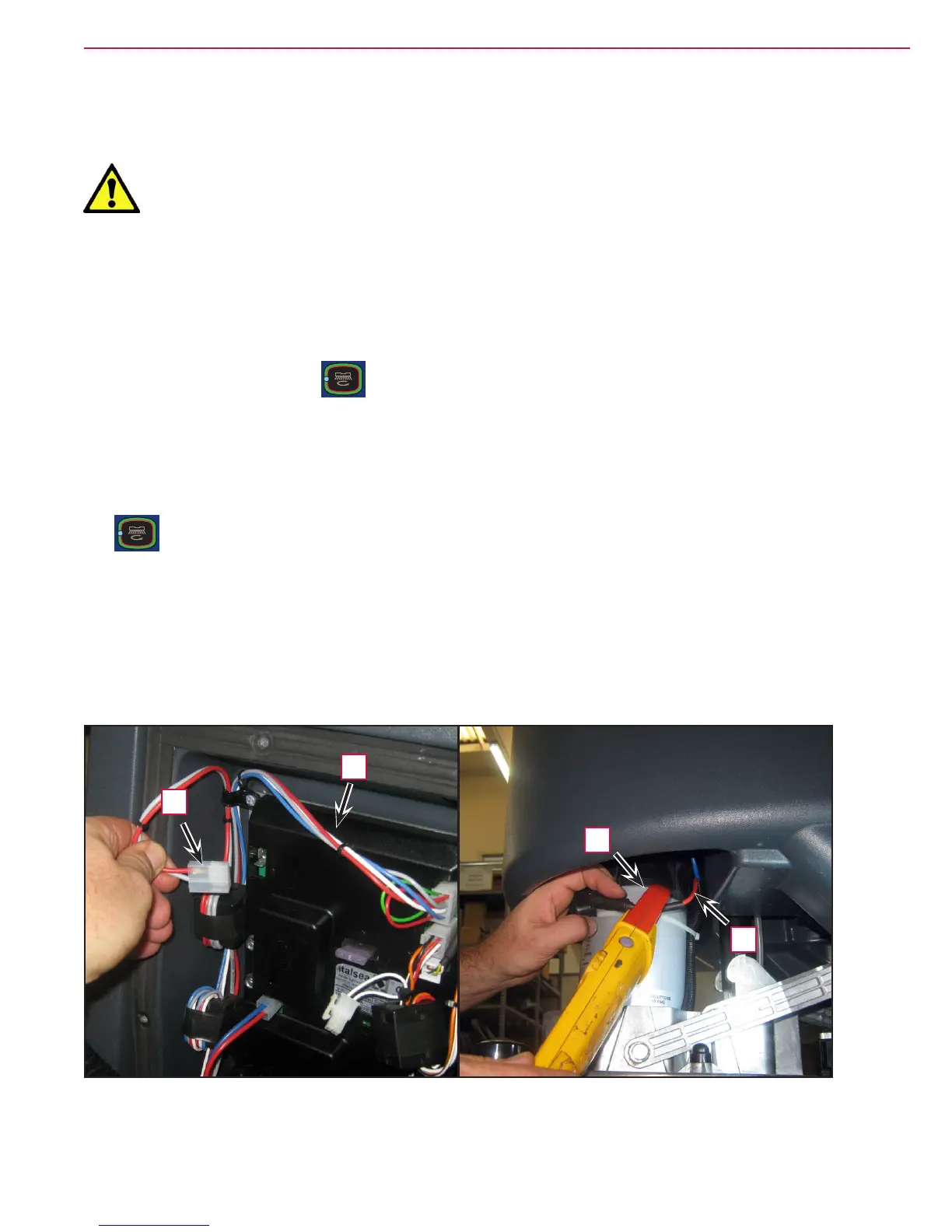
3. Disconnect the drive system connector (A) (Figure 6) on the function board (B) to disable machine
movement.
4. Insert the operator key in its slot on the control panel to switch the machine on.
5. Press the One-Touch button to lower the brush deck.
6. Apply the amperometric clamp (C) to an electrical cable (D) of the brush motor.
7. Activate the brush by pressing the paddle, then check that the brush motor current draw is between 3
and 4A at 20V(*).
8. Deactivate the brush by releasing the paddle and raise the brush deck by pressing the One-Touch button
.
9. Remove the Amp clamp (C).
10. If the amperage is higher, perform the following procedures to detect and correct the abnormal
amperage:
◦ Check the brush motor carbon brushes.
◦ Remove the brush motor then check the condition of its components.
11. If the above-mentioned procedures do not lead to a correct amperage, it is necessary to replace the brush
motor.
Figure 6
D
B
C
A
(*) Voltage value supplied by the electronic board to the brush gear motor when the gear motor current draw
is less than the value of the RPM parameter.

 Loading...


