Electrical System 58Service Manual – SC500
Battery Charge State Display
(Signicant levels for machine operation)
INDICATION
TRANSITION THRESHOLD (VOLT)
CONSEQUENCE
WET GEL
1 22V 22.2V Little remaining run time, no block.
2 20.4V 21.6V Brush OFF
3 19.4V 20.6V Vacuum system OFF
4 18.4V 19.6V Drive system OFF
Checking/Replacing Fuses
1. Drive the machine on a level oor.
2. Remove the operator key.
3. Disconnect the red battery connector.
4. Lift the recovery tank.
5. Remove the 7 screws and remove the electronic component compartment cover.
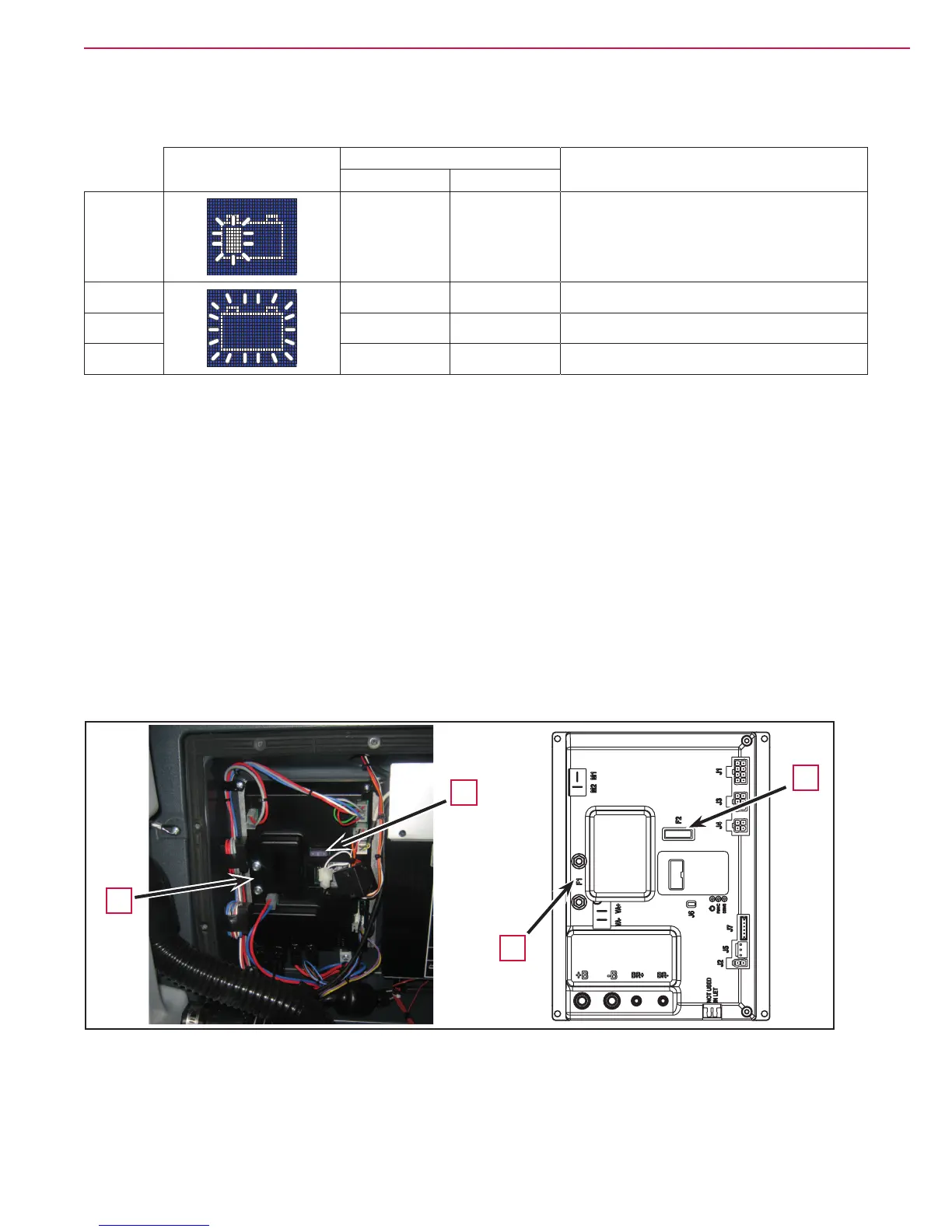
6. Check/replace the following fuses (Figure 7):
◦ (F1) 100A midi fuse - function board (A).
◦ (F2) 3A blade fuse - Signal circuits (B).
7. Place the function electronic board assembly in its housing, tighten the mounting screws and install the
electronic component compartment cover.
Figure 7
B
B
A
A

 Loading...


