Control System 19Service Manual – SC500
Control System
Functional Description
The architecture of the electronic control system for
the machine’s electrical components is composed of
a Function Board (EB1) and a Display Board (EB2),
in turn connected to a Dashboard Instrument Board
(EB3) which represents the main user interface.
The function board (EB1) manages all components
and drives the following components directly:
- Drive system motor (M3)
- Vacuum system motor (M2)
- Deck actuator (M5)
- Brush motor (M6)
- Solution ow solenoid valve (EV1)
- Detergent pump (M4)
The Display Board (EB2) serves mainly as an ag-
gregator for all input signals (buttons) and outputs
(LEDs) from the Dashboard Instrument Board (EB3),
which it is connected to via 2 at cables.
Mounted on the Display Board (EB2) is also the LCD
display and the 2 sensors which detect the presence
and type of magnetic key inserted in the dashboard.
The display electronic board (EB2) sends all the input
and output signals of these components to the func-
tion electronic board (EB1) using 2-wire 2-way serial
communications protocol.
The system is completed by the on-board battery
charger which also uses a proprietary serial protocol
to communicate with the Function Board (EB1), in or-
der to display its operating status (charging phase) to
the operator on the LCD display.
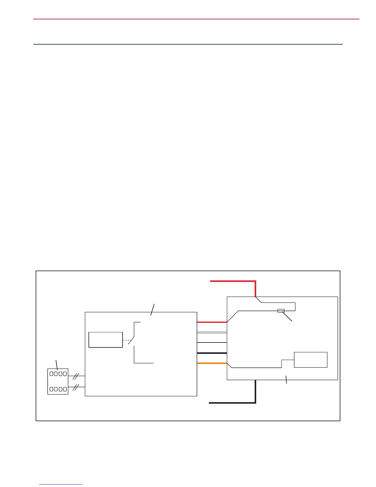
Wiring Diagram
J1.5
J1.4
J1.3
J1.2
J1.1
J3
J2
J3.1
J3.2
J3.3
J3.4
J3.5
Dashboard power supply +
Dashboard serial +
Dashboard serial -
Dashboard power supply -
Return from key
FCI DUFLEX (2.54 pitch) 8-way, male pins
FCI DUFLEX (2.54 pitch) 9-way, male pins
Dashboard power supply +
Dashboard serial +
Dashboard serial -
Dashboard power supply -
Return from key
B-
B+
SCHEDA DISPLAY (EB2)
BATT +
BATT -
Microprocessor
Microprocessor
SIGNAL CIRCUITS
FUSE (F2)
FUNCTION ELECTRONIC
BOARD (EB1)
DASHBOARD
INSTRUMENT
BOARD (EB3)
Figure 1

 Loading...


