Control System 45Service Manual – SC500
Shop Measurements - Function Board (EB1) (continues)
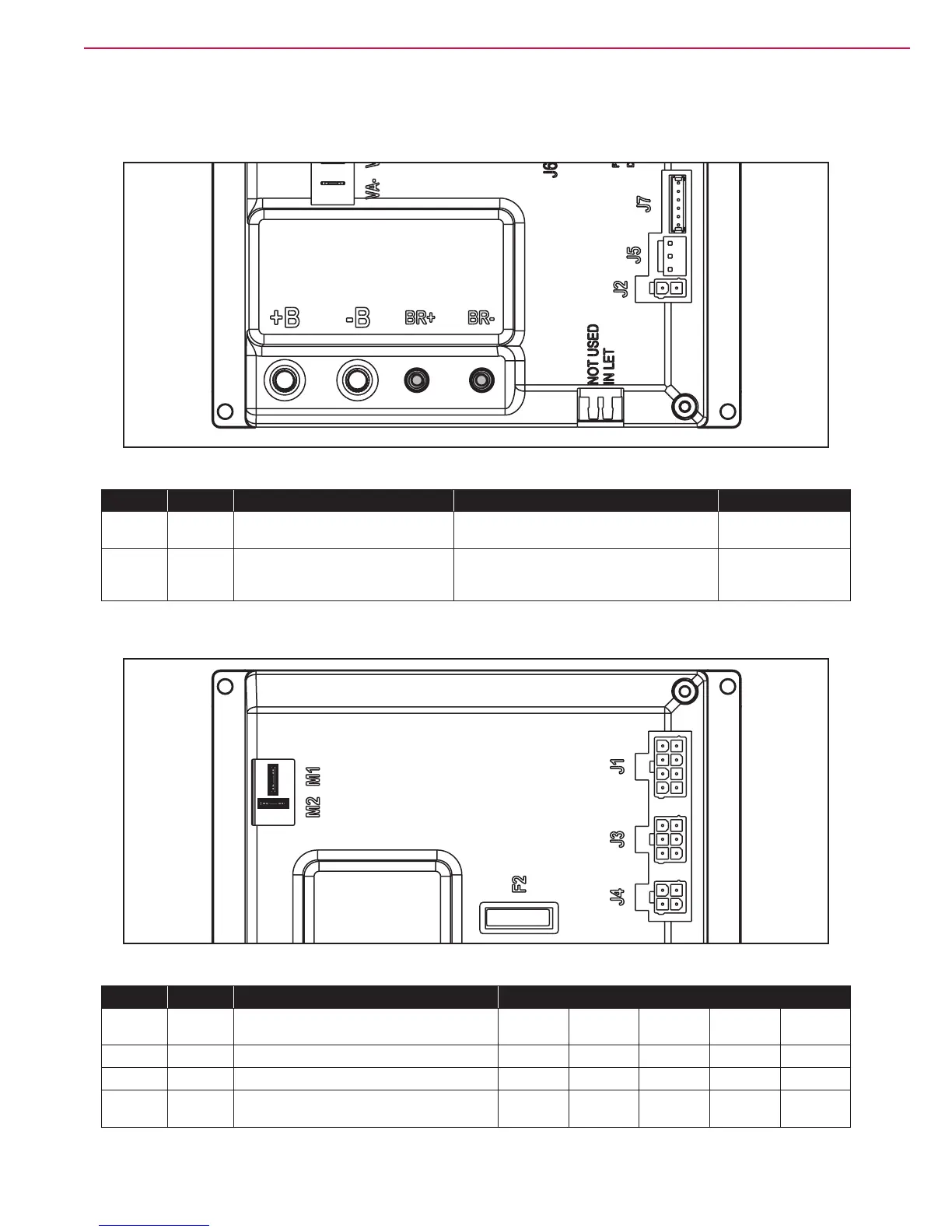
Brush Motor
Figure 34
PIN Color Description Measured Comments
BR+ Red Brush motor + 24.4V (off),
24.2V (on)
Constant Positive
BR- Blue Brush motor - 24.4V (off),
0.15v (on without RPM control activated)
5.8v (on with RPM Control Active – set at 20)
PWM Battery
Negative
Drive System Motor
Figure 35
PIN Color Circuit Description Measured
Neutral Fwd -
Initial
Reverse -
Initial
FWD Max REV Max
M1 Red Drive system motor + 5.62v 12.7v 10.9v 21.8v 8.7v
M2 Gray Drive system motor - 5.61 1.95 16.00 8.9v 13.5v
M1 to
M2
0.001v 6.1v -2.5v 22.6 -7.4

 Loading...


