NSW-5
Disassembly and Troubleshooting Instructions
PAMS Technical Documentation
Page 27
Issue 1 10/00
Nokia Mobile Phones Ltd.
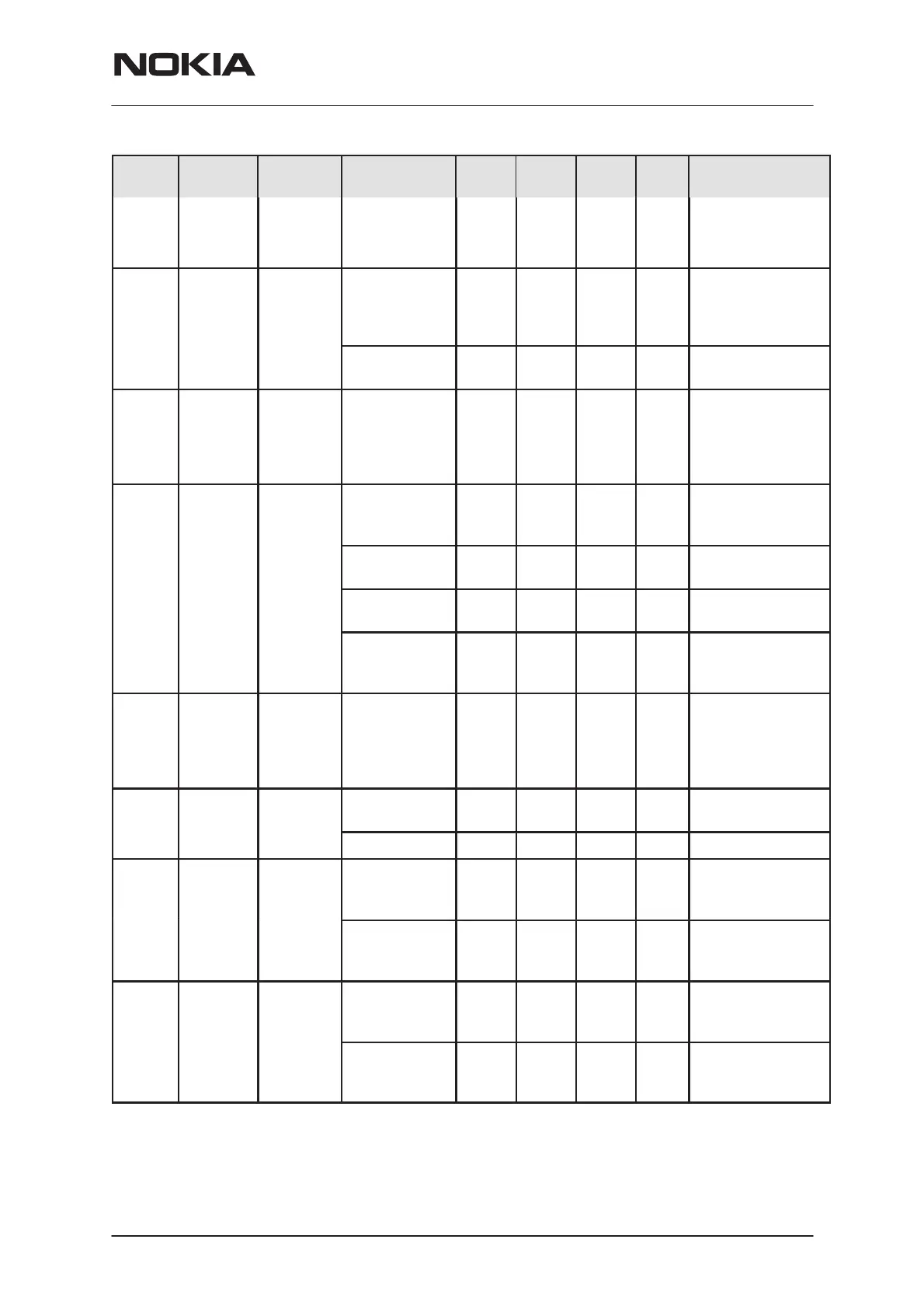
FunctionUnitMaxTypMinParameterToFromSignal
name
RSSI EROTUS CCONT/
COB-
BA_D
Output level 0.1 1.5 V Analog mode field
strenght indicator
TXIP/
TXIN
COBBA EROTUS
Differential
voltage swing
(static)
0.62 0.82 Vpp Differential in–
phase TX base-
band signal for the
RF modulator
Single ended
output level
0.760 0.8 0.84 V
TXQP/
TXQN
COBBA EROTUS Same as
TXIP/TXIN
Differential quad-
rature phase TX
baseband signal
for the RF modu-
lator
TXC COBBA EROTUS
Number of bits 10 bits Transmitter power
control (ramps &
power levels)
Output voltage
swing
2.09 2.15 2.21 V
Minimum code
output level
0.12 0.15 0.18 V
Maximum
code output
level
2.27 2.3 2.33 V
TXF EROTUS MAD Voltage 0 2.85 V False transmis-
sion indicator,
function controlled
via EROTUS reg-
ister
TXP2 MAD PENTA
regulator
Logic high ”1” 2.0 V 2 Ghz Transmitter
enable
Logic low ”0” 0.5 V VR11 ON/OFF
TXA MAD EROTUS
Logic high ”1” 2.0 V PWR control loop
during TX burst
(slow mode)
Logic low ”0” 0.5 V PWR control loop
during ramp up/
down (fast mode)
TXLX1 MAD TX 800
Logic high ”1” 2.1 2.85 V Low power level
mode for power
detector
Logic low ”0” 0 0.6 V High power level
mode for power
detector

 Loading...


