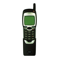
NSW-5
Disassembly and Troubleshooting Instructions
PAMS Technical Documentation
Page 28
Issue 1 10/00
Nokia Mobile Phones Ltd.
FunctionUnitMaxTypMinParameterToFromSignal
name
TXLX2 MAD
TX 1900 Logic high ”1” 2.1 2.85 V Low power level
mode for power
detector
Logic low ”0” 0 0.6 V High power detec-
tor mode power
detector
SENA2 MAD
2 Ghz
UHF PLL
Logic high ”1” 2.0 2.85 V 2 Ghz PLL enable
Logic low ”0” 0 0.8 V
RXPW
R2
MAD
PENTA Logic high ”1” 2.0 V VR8 ON, 1Ghz
frontend
Logic low ”0” 0 0.5 V VR8 OFF
RXPW
R3
MAD
PENTA Logic high ”1” 2.0 V VR9 ON 2Ghz
frontend
Logic low ”0” 0 0.5 V VR9 OFF
SPWR
3
COB-
BA_D
PENTA Logic high ”1” 2.0 V VR10 ON , 2Ghz
UHF
Logic low ”0” 0 0.5 V VR10 OFF
TXPW
R1
MAD
CCont Logic high ”1” 2.0 V VR5 ON , TX pwr
control enable
Logic low ”0” 0 0.5 V VR5 OFF
TXWR
2
MAD
PENTA Logic high ”1” 2.0 V VR12 ON ,
TDMA1900 TX–
upconverter en-
able
Logic low ”0” 0 0.5 V VR12 OFF
TXWR
3
MAD TDMA800
TX–up-
converter
Logic high ”1” 2.0 V AMPS &
TDMA800 TX–up-
converter enable
Logic low ”0” 0 0.5 V TX–UC disable
VR1 CCont RF Voltage 2.7 2.8 2.9 V Supply for
VCTCXO, Erotus
VHF prescaler
and bias, and
2 GHz PLL
VR2 CCont RF Voltage 2.7 2.8 2.9 V Supply voltage for
1GHZ UHF VCO
and prescaler
VR3 CCont RF Voltage 2.7 2.8 2.9 V Supply voltage for
VHF VCO, LO
buffer, 1 Ghz TX–
mixer and power
detector
VR4 CCont RF Voltage 2.7 2.8 2.9 V Supply voltage for
EROTUS IF–parts
and IF–amplifier

 Loading...