24 EV2 Series DVR
VI. SETUP
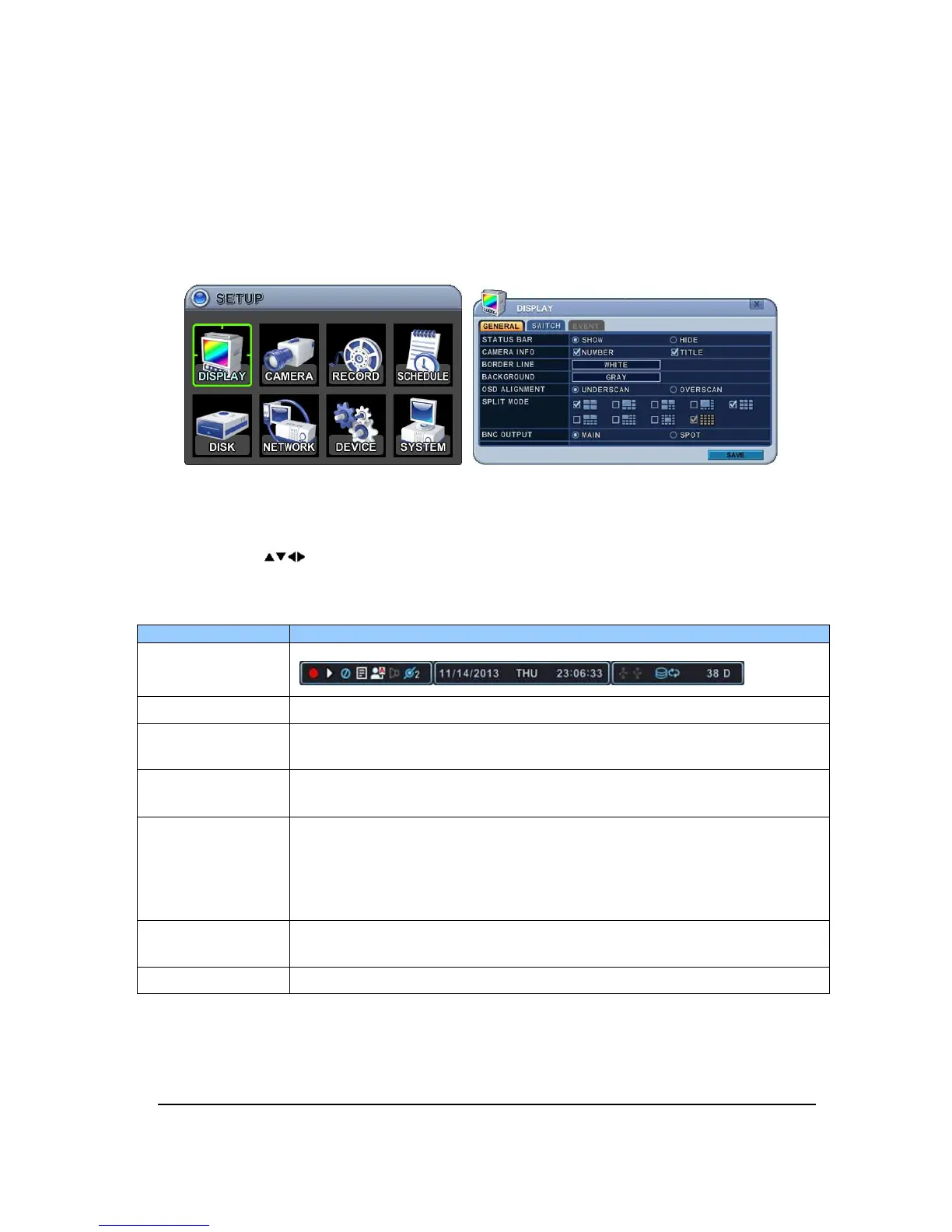
1. DISPLAY
1.1. GENERAL
1. The menus are displayed with options on the left-hand column and settings in the
right hand column. A cursor (highlighted menu) can be moved using the Direction
buttons [ ].
2. Change below options using [DEC/INC] buttons.
ITEM ADJUSTMENT
STATUS BAR
Select “Show” or “Hide” below status bar on Main Monitor.
CAMERA INFO
Select On-Screen-Display information for Camera Number and Title.
BORDER LINE
Select Board Line between cameras.
[GRAY
WHITE
BLUE
BLACK
DARK GRAY]
BACKGROUND
Select Background color on NO VIDEO status.
[GRAY
WHITE
BLUE
BLACK
DARK GRAY]
OSD ALIGNMNET
The main video output can be displayed on a VGA and analog monitor.
Video can be displayed on both monitor simultaneously. Select On-
Screen-Display coordinates on Monitor.
- Over scan: Displays properly at CCTV Monitors.
SPLIT MODE
Display is changed the order as shown below among your choice of
SPLIT MODE.
BNC OUTPUT
Select “MAIN” for Composite or “SPOT” for Spot on Video out.
3.
Select SAVE to save changes and press [ENTER] button to exit the menu.
Exit the menu without making changes, press [CANCEL] button.