MS51
Nov. 28, 2019 Page 230 of 491 Rev 1.00
MS51 32K SERIES TECHNICAL REFERENCE MANUAL
6.2.6 Interrupt System
Overview 6.2.6.1
The purpose of the interrupt is to make the software deal with unscheduled or asynchronous events.
The MS51 has a four-priority-level interrupt structure with 24 interrupt sources. Each of the interrupt
sources has an individual priority setting bits, interrupt vector and enable bit. In addition, the interrupts
can be globally enabled or disabled. When an interrupt occurs, the CPU is expected to service the
interrupt. This service is specified as an Interrupt Service Routine (ISR). The ISR resides at a
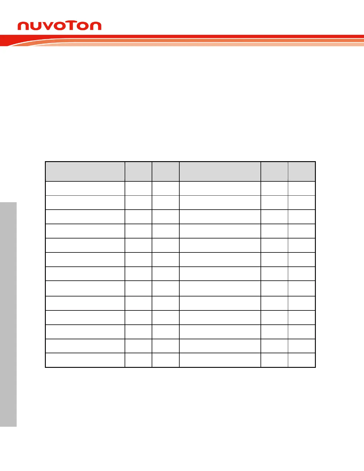
predetermined address as shown in Table 6.2-3 Interrupt Vectors. When the interrupt occurs if
enabled, the CPU will vector to the respective location depending on interrupt source, execute the
code at this location, stay in an interrupt service state until the ISR is done. Once an ISR has begun, it
can be interrupted only by a higher priority interrupt. The ISR should be terminated by a return from
interrupt instruction RETI. This instruction will force the CPU return to the instruction that would have
been next when the interrupt occurred.
Self Wake-up Timer interrupt
I
2
C status/timer-out interrupt
Brown-out detection interrupt
Table 6.2-3 Interrupt Vectors
Enabling Interrupts 6.2.6.2
Each of individual interrupt sources can be enabled or disabled through the use of an associated
interrupt enable bit in the IE and EIE0 SFR. There is also a global enable bit EA bit (IE.7), which can
be cleared to disable all the interrupts at once. It is set to enable all individually enabled interrupts.
Setting the EA bit to logic 0 disables all interrupt sources regardless of the individual interrupt-enable
settings. Note that interrupts which occur when the EA bit is set to logic 0 will be held in a pending
state, and will not be serviced until the EA bit is set back to logic 1. All interrupt flags that generate