MS51
Nov. 28, 2019 Page 29 of 491 Rev 1.00
MS51 32K SERIES TECHNICAL REFERENCE MANUAL
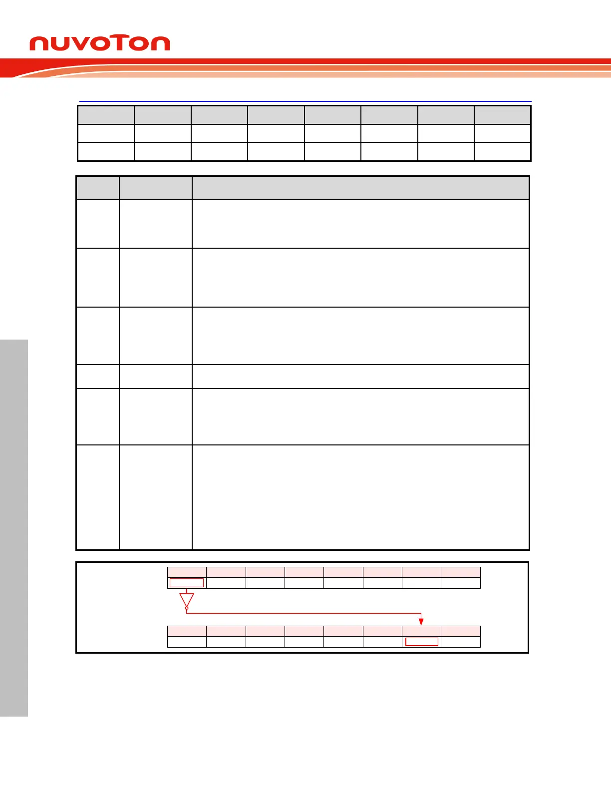
CONFIG0
Factory default value: 1111 1111b
CONFIG boot select
This bit defines from which block that MCU re-boots after resets except software reset.
1 = MCU will re-boot from APROM after resets except software reset.
0 = MCU will re-boot from LDROM after resets except software reset.
PWM output state under OCD halt
This bit decides the output state of PWM when OCD halts CPU.
1 = Tri-state pins those are used as PWM outputs.
0 = PWM continues.
Note that this bit is valid only when the corresponding PIO bit of PWM channel is set as 1.
OCD enable
1 = OCD Disabled.
0 = OCD Enabled.
Note: If MCU run in OCD debug mode and OCDEN = 0, hard fault reset will disable. Only
HardF flag be asserted.
Reset pin disable
1 = The reset function of P2.0/nRST pin Enabled. P2.0/nRST functions as the external reset
pin.
0 = The reset function of P2.0/nRST pin Disabled. P2.0/nRST functions as an input-only pin
P2.0.
Chip lock enable
1 = Chip is unlocked. Flash Memory is not locked. Their contents can be read out through a
parallel Writer/ICP programmer.
0 = Chip is locked. Whole Flash Memory is locked. Their contents read through a parallel
Writer or ICP programmer will be all blank (FFH). Programming to Flash Memory is invalid.
Note that CONFIG bytes are always unlocked and can be read. Hence, once the chip is
locked, the CONFIG bytes cannot be erased or programmed individually. The only way to
disable chip lock is execute “whole chip erase”. However, all data within the Flash Memory
and CONFIG bits will be erased when this procedure is executed.
If the chip is locked, it does not alter the IAP function.
CHPCON
CONFIG0
CBS
7
-
6
OCDPWM
5
OCDEN
4
-
3
RPD
2
LOCK
1
-
0
SWRST
7
IAPFF
6
-
5
-
4
-
3
-
2
BS
1
IAPEN
0
Software reset does not reload
Figure 6.1-3. CONFIG0 Any Reset Reloading