MS51
Nov. 28, 2019 Page 409 of 491 Rev 1.00
MS51 32K SERIES TECHNICAL REFERENCE MANUAL
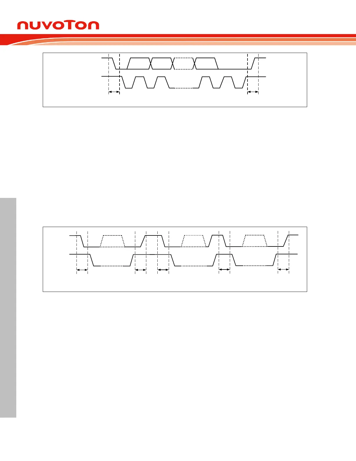
SDA
SCL
MSB
LSB
ACK
1
2 8 9
START
condition
STOP
condition
Figure 6.11-2 I
2
C Bus Protocol
START and STOP Condition 6.11.2.1
The protocol of the I
2
C bus defines two states to begin and end a transfer, START (S) and STOP (P)
conditions. A START condition is defined as a high-to-low transition on the I2C0_SDA line while
I2C0_SCL line is high. The STOP condition is defined as a low-to-high transition on the I2C0_SDA line
while I2C0_SCL line is high. A START or a STOP condition is always generated by the master and I
2
C
bus is considered busy after a START condition and free after a STOP condition. After issuing the
STOP condition successful, the original master device will release the control authority and turn back
as a not addressed slave. Consequently, the original addressed slave will become a not addressed
slave. The I
2
C bus is free and listens to next START condition of next transfer.
A data transfer is always terminated by a STOP condition generated by the master. However, if a
master still wishes to communicate on the bus, it can generate a repeated START (Sr) condition and
address the pervious or another slave without first generating a STOP condition. Various combinations
of read/write formats are then possible within such a transfer.
SDA
SCL
START STOP
START
Repeated
START
STOP
Figure 6.11-3 START, Repeated START, and STOP Conditions
7-Bit Address with Data Format 6.11.2.2
Following the START condition is generated, one byte of special data should be transmitted by the
master. It includes a 7-bit long slave address (SLA) following by an 8
th
bit, which is a data direction bit
(R/W), to address the target slave device and determine the direction of data flow. If R/W bit is 0, it
indicates that the master will write information to a selected slave. Also, if R/W bit is 1, it indicates that
the master will read information from the addressed slave. An address packet consisting of a slave
address and a read I or a write (W) bit is called SLA+R or SLA+W, respectively. A transmission
basically consists of a START condition, a SLA+W/R, one or more data packets and a STOP
condition. After the specified slave is addressed by SLA+W/R, the second and following 8-bit data
bytes issue by the master or the slave devices according to the R/W bit configuration.
Figure 6.11-4 shows a master transmits data to slave by 7-bit. A master addresses a slave with a 7-bit
address and 1-bit write index to denote that the master wants to transmit data to the slave. The master
keeps transmitting data after the slave returns acknowledge to the master.