MS51
Nov. 28, 2019 Page 299 of 491 Rev 1.00
MS51 32K SERIES TECHNICAL REFERENCE MANUAL
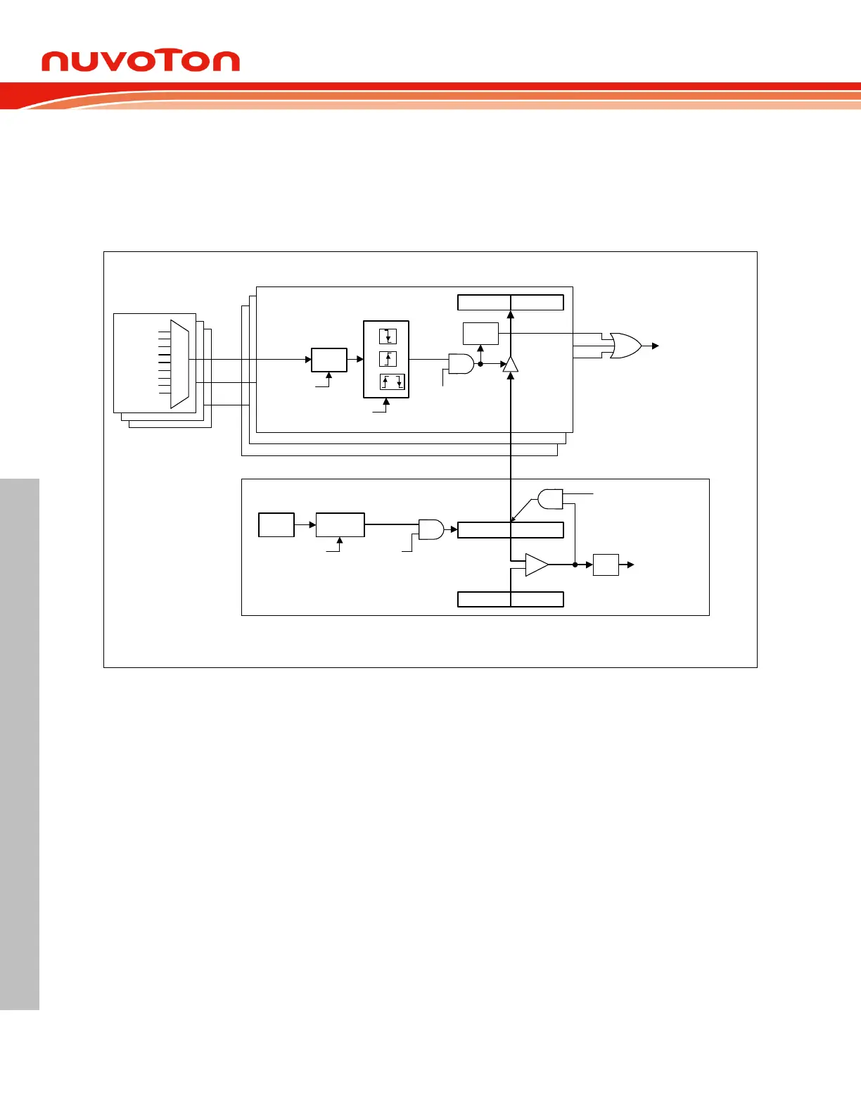
Compare Mode 6.5.2.3
Timer 2 can also be configured as the compare mode by setting CM/RL2
. In this mode RCMP2H and
RCMP2L registers serve as the compare value registers. As Timer 2 up counting, TH2 and TL2 match
RCMP2H and RCMP2L, TF2 (T2CON.7) will be set by hardware to indicate a compare match event.
Setting CMPCR (T2MOD.2) makes the hardware to clear Timer 2 counter as 0000H automatically
after a compare match has occurred.
Input Capture Interrupt
CAPF0
CAPF1
CAPF2
TF2
Timer 2 Interrupt
Pre-scalarF
SYS
RCMP2H
T2DIV[2:0]
(T2MOD[6:4])
RCMP2L
TH2
TL2
TR2
(T2CON.2)
Timer 2 Module
CMPCR
(T2MOD.2)
Clear Timer 2
=
C0HC0L
Noise
Filter
ENF0
(CAPCON2.4)
or
[00]
[01]
[10]
CAP0LS[1:0]
(CAPCON1[1:0])
CAPEN0
(CAPCON0.4)
CAPF0
Input Capture 0 Module
Input Capture 1 Module
Input Capture 2 Module
CAP0
CAP1
CAP2
0000
0001
0010
0011
0100
0101
0110
0111
P1.5/IC7
P0.5/IC6
P0.3/IC5
P0.1/IC4
P0.0/IC3
P1.0/IC2
P1.1/IC1
P1.2/IC0
1000
P0.4/IC3
Figure 6.5-7 Timer 2 Compare Mode and Input Capture Module Functional Block Diagram