MS51
Nov. 28, 2019 Page 430 of 491 Rev 1.00
MS51 32K SERIES TECHNICAL REFERENCE MANUAL
Respectively, the MISO is used to receive a serial data from the Slave to the Master.
The SPCLK pin is the clock output in Master mode, but is the clock input in Slave mode. The shift
clock is used to synchronize the data movement both in and out of the devices through their MOSI and
MISO pins. The shift clock is driven by the Master mode device for eight clock cycles. Eight clocks
exchange one byte data on the serial lines. For the shift clock is always produced out of the Master
device, the system should never exist more than one device in Master mode for avoiding device
conflict.
Each Slave peripheral is selected by one Slave Select pin (SS
). The signal should stay low for any
Slave access. When SS
is driven high, the Slave device will be inactivated. If the system is multi-
slave, there should be only one Slave device selected at the same time. In the Master mode MCU, the
SS
pin does not function and it can be configured as a general purpose I/O. However, SS
can be used
as Master Mode Fault detection (see chapter 6.12.5 Mode Fault Detection) via software setting if
multi-master environment exists. The MS51 also provides auto-activating function to toggle SS
between each byte-transfer.
MISO
MOSI
SPCLK
SS
I/O
PORT
0
1
2
3
I/O
PORT
0
1
2
3
SO
SI
SCK
SS
Slave device 1
Master/Slave
MCU1
MISO
MOSI
SPCLK
SS
Master/Slave
MCU2
SO
SI
SCK
SS
Slave device 2
SO
SI
SCK
SS
Slave device 3
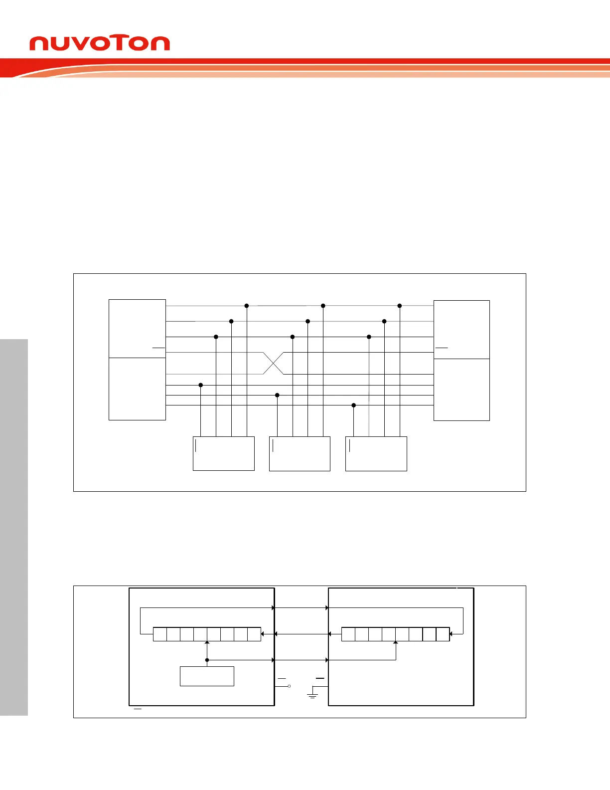
Figure 6.12-2 SPI Multi-Master, Multi-Slave Interconnection
Figure 6.12-2 shows a typical interconnection of SPI devices. The bus generally connects devices
together through three signal wires, MOSI to MOSI, MISO to MISO, and SPCLK to SPCLK. The
Master devices select the individual Slave devices by using four pins of a parallel port to control the
four SS
pins. MCU1 and MCU2 play either Master or Slave mode. The SS
should be configured as
Master Mode Fault detection to avoid multi-master conflict.
SPI clock
generator
MISO MISO
MOSI MOSI
SPCLK SPCLK
GND
SS SS
7 6 5 4 3 2 1 0
SPI shift register
7 6 5 4 3 2 1 0
SPI shift register
Master MCU Slave MCU
*
* SS configuration follows DISMODF and SSOE bits.
Figure 6.12-3 SPI Single-Master, Single-Slave Interconnection
 Loading...


