MS51
Nov. 28, 2019 Page 289 of 491 Rev 1.00
MS51 32K SERIES TECHNICAL REFERENCE MANUAL
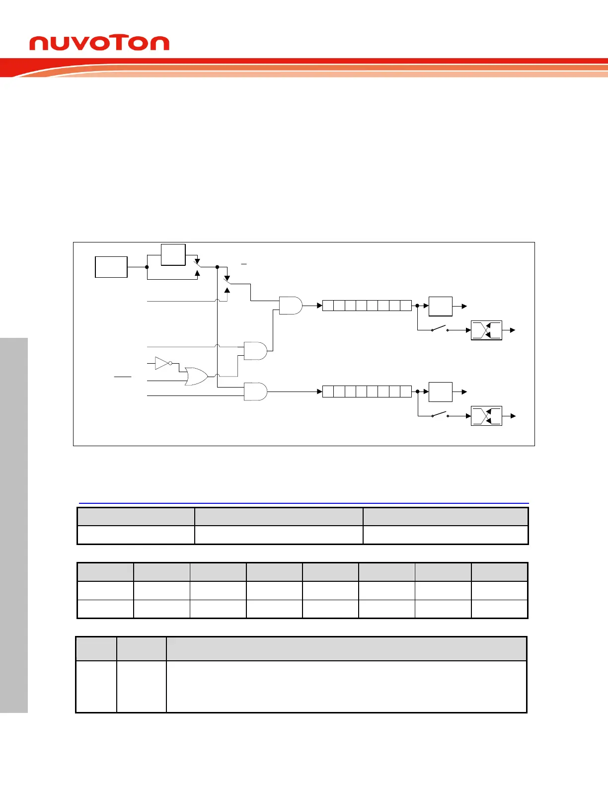
Mode 3 (Two Separate 8-Bit Timers) 6.5.1.5
Mode 3 has different operating methods for Timer 0 and Timer 1. For Timer/Counter 1, Mode 3 simply
freezes the counter. Timer/Counter 0, however, configures TL0 and TH0 as two separate 8 bit count
registers in this mode. TL0 uses the Timer/Counter 0 control bits C/T
, GATE, TR0, INT0
, and TF0.
The TL0 also can be used as a 1-to-0 transition counter on pin T0 as determined by C/T
(TMOD.2).
TH0 is forced as a clock cycle counter and takes over the usage of TR1 and TF1 from Timer/Counter
1. Mode 3 is used in case that an extra 8 bit timer is needed. If Timer/Counter 0 is configured in Mode
3, Timer/Counter 1 can be turned on or off by switching it out of or into its own Mode 3. It can still be
used in Modes 0, 1 and 2 although its flexibility is restricted. It no longer has control over its overflow
flag TF1 and the enable bit TR1. However Timer 1 can still be used as a Timer/Counter and retains
the use of GATE, INT1
pin and T1M. It can be used as a baud rate generator for the serial port or
other application not requiring an interrupt.
TF0
TH0
TL0
Timer 0 Interrupt
0 7
0 7
TF1
Timer 1 Interrupt
TR1
GATE
TR0
INT0 pin
T0 pin
T0OE
T1 pin
T1OE
0
1
T0 pin
C/T
F
SYS
1/12
0
1
T0M
Figure 6.5-4 Timer/Counter 0 in Mode 3
Control Registers of I/O Ports 6.5.1.6
TMOD – Timer 0 and 1 Mode
Timer 1 gate control
0 = Timer 1 will clock when TR1 is 1 regardless of INT1
logic level.
1 = Timer 1 will clock only when TR1 is 1 and INT1
 Loading...


